Charles J. Hazouri
Level III Infraspection CIT, Certified Marine Surveyor
Offshore Marine Inspections
500 Mandeville Street, Unit 10 New Orleans, LA 70117Ph: 504-450-8044 www.offshorenola.comAbstract
Inspection techniques such as infrared thermography, ultrasonic testing, and visual inspections using unmanned aerial vehicles (drones), have changed the face of marine inspections/surveys. Not so long ago, these technologies were unheard of and beyond the budget of many surveyors; however, recent advances in technology have made such test equipment quite affordable. Combined with greater public awareness, these tests are rapidly becoming an integral part of marine inspections / surveys. This article will focus on the application and benefits of infrared thermography as a tool for the marine surveyor.
Introduction
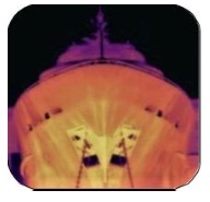 What is Thermography? Thermography or thermal imaging is the use of a thermal imaging system to detect, display, and record thermal patterns and temperatures across the surface of an object. Thermal imagers convert the heat given off by all objects into a two-dimensional monochrome or multi-color image wherein thermal patterns are represented by varying shades of grey or color. Thermal imagery may be viewed in real time on the imager’s monitor or it may be recorded to video, electronic media, or used to produce a hardcopy print known as a thermogram.
Discussion
For marine vessels, thermal imaging may be applied to hulls, structural materials, and features made of composites, electrical system components, and mechanical equipment. In order for thermography to be effective, thermal imaging must be carried out under proper conditions, and one must have direct line-of-sight access to the surface of objects or areas to be imaged.
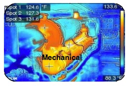 Thermography and Marine Inspections: Chief among the many benefits of thermal imaging is that it is a non-invasive inspection technique that can detect hidden anomalies or problems within a vessel’s structure. The nondestructive nature of the technique makes it a perfect tool for marine inspections. Depending upon one’s circumstances, thermography may be used for condition assessment during surveys or it may be used to detect problems during either construction or repair. When applying thermography in a marine survey and/or inspection, it is imperative to understand the principles of thermal imaging and heat transfer. One should also have knowledge of marine vessel construction and physics, composites, and marine electrical and mechanical systems.
Experience Matters: The proliferation of inexpensive thermal imagers has helped to spur interest in thermography for marine applications. While thermal imagers are relatively easy to operate, thermography is not a ‘point and shoot’ technology. Proper application of the technology and interpretation of the results requires special training in heat transfer, infrared theory, and image interpretation.
Thermography is both art and science and success is largely dependent upon the skills of the operator or Thermographer. As with any profession, the more trained and prepared those who attempt it are, the better the results. I was inspired to write this article because I have recently seen some troubling practices in the field of thermal imaging.
Marine inspectors who are untrained in thermography can represent the industry poorly, especially when they use thermal imaging equipment that is inappropriate for the application or they misinterpret the imagery they collect. To help ensure inspection accuracy, boat owners or marine repair professionals should make certain that thermal imaging is conducted by a Certified Infrared Thermographer.
Conducting the Inspection: In order to ensure success, it is necessary to know a few basic facts about the vessel in order to correctly set up the thermal imager. These include the emissivity of the area being imaged, atmospheric conditions including ambient temperature, relative humidity, and reflected temperature. It is also important to note any artificial lighting and external heat sources which could affect the inspection.
Emissivity refers to the amount of radiation emitted from an object compared to that of a perfect emitter or blackbody at the same wavelength and temperature. Reflected Temperature is the apparent temperature value reported by a radiometer that corresponds to the infrared energy incident upon and reflected from the measured surface of an object.1
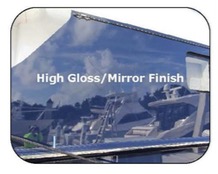 In addition, I also like to note a few other factors during an inspection such as the gloss readings using a TQC Gloss Meter, which gives me an idea of how pronounced reflections may be. Where appropriate, moisture content is noted using an Aquant Protimeter non-invasive moisture meter. A visual inspection is done throughout this process to ensure that any outward damage or anomaly is noted and thoroughly examined. I also provide a complete sounding of the areas examined with a phenolic hammer. All of these factors are described carefully in my final, detailed report.
Thermal imaging in marine inspections is generally done to find anomalies. An anomaly is a term to describe something that deviates from what is normal or expected. Thermal anomalies may be caused by moisture ingress, delamination (disbonding), voids, or other defects.
Delamination or Disbonding, in particular, is an area of separation within or between two plies in a laminate or within a bonded joint caused by contamination, improper adhesion during processing, or damaging inter laminar stresses.2A void refers to a situation where air or gas has been trapped and cured in a laminate during the manufacturing process.3
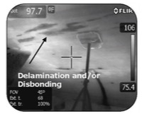 The following inspections and tests were conducted in January 2016 using four, separate thermal imagers: FLIR T440BX Thermal Imager, FLIR E6 Thermal Imager, FLIR C2 Personal Thermal Imager, and the FLIR One Personal Thermal Imager.
Before I proceed to show and explain the images, knowing a few things about the imagers will provide useful information regarding the quality of the images produced. Imager resolution, expressed as the number of pixels (horizontal by vertical) contained within the imager’s detector, serves as a guide regarding the level of detail or clarity that can be expected from a given thermal imager. Generally speaking, greater pixel count equates to higher resolution.
Frame rate, expressed in Hertz, is also important. A frame rate of 60 Hertz allows one to pan across a scene at a faster rate than with imagers having slower frame rates. Imagers with frame rates of less than 30 Hertz are not recommended for documenting rotating machinery and/or a laminate’s response as it reacts to temperature from an externally applied heat source.4
Of the imagers tested: The stand-alone FLIR T440BX has the highest resolution: 320 x 240 (76,800 pixels) and a frame rate of 60 Hertz. Also a stand-alone unit, the FLIR E6 has a resolution of 160 x 120 (19,200 pixels) and a frame rate of 9 Hertz. With a resolution of 80 x 60 (4,800 pixels), the pocket-sized FLIR C2 is a stand-alone unit with a frame rate of 9 Hertz. Available as plug-in module for smart devices, the resolution of the FLIR One is rated at 160 x 120 (19,200 pixels) with a frame rate of 8.5 Hertz. For this article an iOS 9.2.1 iPhone was used.
Referring to the imagers specifications can help to determine the suitability of an imager for a particular inspection.

Conducting the Inspection: In addition to a thermal imager, a heat source is required for infrared inspections of laminates or composites. The purpose of heating the subject material is to create a temperature difference sufficient to allow defects or internal structures to be detected by the imager.
Depending upon the size of the area to be tested, one may use a portable electric or propane heater. The Shrinkfast 998 is a great unit given the fact that it can warm a large area in a short amount of time. Regardless of the heat source chosen, one must be careful not to overheat the subject materials or create a fire hazard.
 Reporting: If a report is to be submitted, it is always best to use a higher resolution imager and proper software. FLIR Tools, FLIR Tools+, and Exception® software ensure that you are able to provide your client a quality product with salient and valid findings, and the ability to visualize all anomalies and structures in clear photographic images. FLIR Tools+ was used for the imagery found in this article.
A properly documented report should include the time of inspection, the weather conditions at the time of the inspection (including the atmospheric temperature and relative humidity), the target emittance (emissivity), reflected temperature, the imager’s serial number and its date of last calibration, and a precise and complete description of the areas that were imaged.
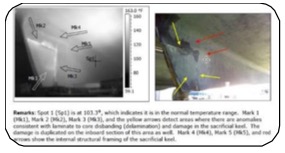
The stand-alone thermal imagers described above were capable of being thermally- tuned using the FLIR Tools + software on a desktop or laptop computer. The FLIR One was only capable of being tuned by using the FLIR tools application on the iOS 9.2.1 iPhone and aftermarket software. Thermally tuning an image allows you to manually adjust the temperature level or span, which is the equivalent to a brightness and contrast adjustment. Thermal tuning can be done on the imager in manual mode or in the software to reduce wash out.
The image on the left is an example of an image from the T440BX that has not been thermally tuned using the computer’s software. As you can see, there are numerous areas of reduced contrast, distortion, and some areas that could be mistaken for anomalies, unlike the image on the right, which has been thermally tuned.

Inspections and Test: The following four grayscale thermal images were taken of a recent repair to the hull of an 80’ Viking Sport Fisherman. These images will demonstrate the different quality of images obtained by using a higher hertz and resolution imager in comparison to an imager with lower hertz and resolution.
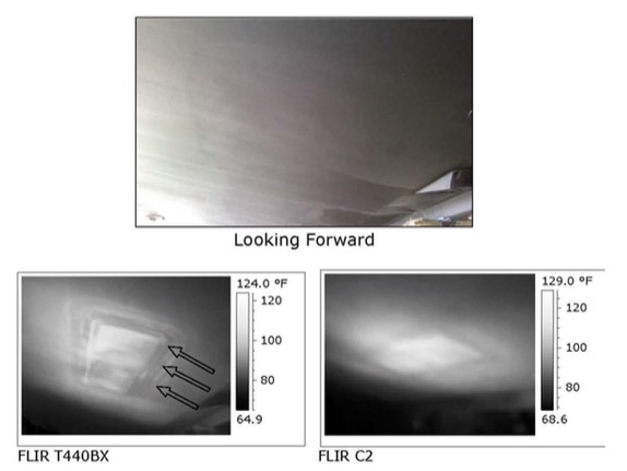
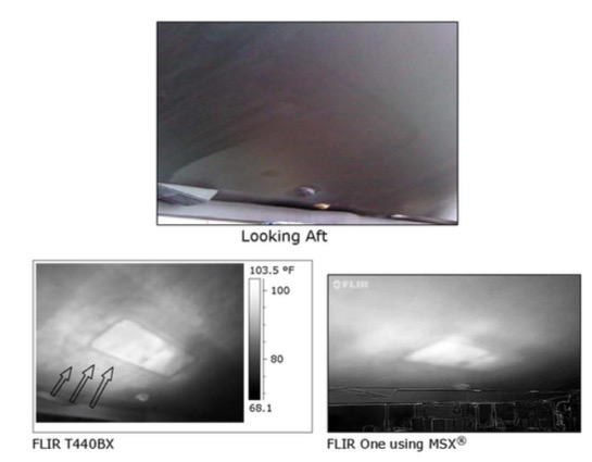
As you can see, the above images show that the T440BX gives you the definition and delineated edges needed for proper inspection. The T440BX actually shows the layers of tabbing for the fiberglass insert, indicated by the black arrows in the images above.
The C2 and FLIR One are too distorted and do not show enough detail and information to do a proper laminate inspection. The FLIR One image could not be thermally tuned using the recommended software in a computer but could be tuned using aftermarket software and the iOS 9.2.1 application. Having an image with specific detail is important for a contractor or boat owner. It documents that repairs are correct and precise.
The following two iron scale thermal images taken of a normal operating battery charger imaged with Multi Spectral Dynamic Imaging or MSX®. MSX® adds key details from the visible light camera to the entire thermal infrared image,v This shows which imager gives enough visual information to do a proper inspection. MSX® does require that you have good visible light for the imager unless you can thermally tune the image using the proper computer software.
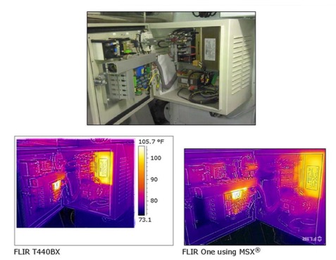
As you can see in these images, the T440BX gives you definition and delineated edges for the electrical inspection. The FLIR One image was slightly distorted. A clearer image is necessary when using MSX® so the inspector can identify the problem area with enough detail to provide useful advice and/or information.
The following eight iron scale thermal images taken of the port side deck fuel fill and cockpit bulwarks of a 72’ Blackwell Boatworks Sport Fisherman will outline and demonstrate which imager is best for moisture ingress and/or water intrusion in fiberglass laminates.
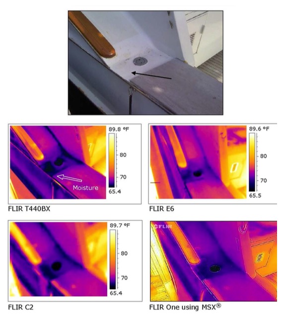
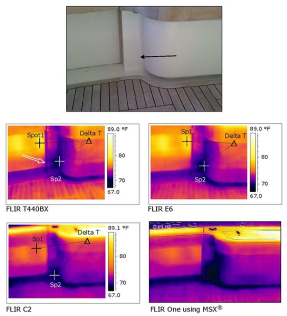
As you can see, the T440BX gives you the best definition and delineated edges for the inspection. With the Spot1 (Sp1) and Sp2 temperature readings, the T440BX and E6 show close to a ten degree Fahrenheit temperature difference, while the C2 showed just under a six degree temperature difference. The E6 is slightly distorted while the C2 and FLIR One are quite distorted and do not show what you need to do a proper inspection by defining the actual area of concern as indicated by the black and white arrows. An actual Delta T could not be determined in the FLIR One image.
The following two grayscale thermal images taken of the carbon fiber keel flange of a 52’ Transpac TP52 Sailboat will outline and demonstrate which imager is best for vessels constructed of carbon fiber.
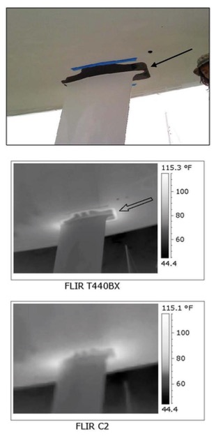
The above images show that the T440BX gives you the best definition and delineated edges for good inspection. The C2 is distorted and does not show what you need to do a proper inspection.
Conclusion
Based on the imagery in these inspections and tests, thermography, or thermal imaging, can clearly identify and document the thermal patterns of laminates when used in the structural capacity of vessel repair or construction, and in the case of product failure such as moisture intrusion, delamination (disbonding), and voids.
The Marine Surveyor has a choice in the equipment which he/she chooses to use for their inspections, and how they want to present themselves through the quality of their reports and inspections.
Higher resolution imagers do a much better job for the professional Thermographer and/or Marine Surveyor. Higher resolution imagers having frame rates greater than 30 Hertz are the perfect tool for marine inspections as they provide graphic information not available by other means.
 Lower resolution imagers may be adequate for inspections of electrical and mechanical equipment and are an inexpensive tool to have in one’s arsenal of inspection tools. They did not, in these inspections, do an adequate job in detecting problems within laminates.
Due to the complex and subjective nature of thermal imaging, it is highly recommended that any inspector, surveyor, or project manager using thermal imaging be properly trained in the field of infrared thermography.
A Certified Level I Infrared Thermographer should be considered by the boat owner, contractor, legal or insurance professional, and marine surveyor prior to any inspection process involving thermal imaging. In addition, an inspector should have a detailed and in-depth knowledge of vessel construction and physics.
For the same reason a boat owner or maritime professional would require a Certified Marine Surveyor, Surveyor Associate, and/or Accredited Marine Surveyor to do a basic visual vessel inspection, proper certification for thermal imaging is essential. Infraspection Institute and Infrared Training Center are two reputable training facilities.
A properly trained and qualified Thermographer can provide a boat owner, sub- contractor, and/or marine surveyor a detailed report that will potentially save them time and money in the initial inspection, repair, post-repair, and construction processes. Sub-standard imaging and reporting can cost your client more in the long run. Be precise and accurate in your findings and remember:
“Magic comes from the Thermographer, not the Imager.”6
Special thanks and considerations to:
Dennis Foster of Fosters Yacht Services
Sean Hodgson of DFD-Drawings Fabrications and Details, Inc.
Nate Goodman of All Points Boats, Inc.
Captain Jason Downing of the Motor Yacht (M/Y) Pure Insanity, for their donation of the inspected vessels
James Seffrin, Director of Infraspection Institute
Lynda H. Cobb, Editor
1. Infraspection Institute, Standard for Measuring and Compensating for Reflected Temperature Using Infrared Imaging Radiometers, 2011 Edition.
2. Infraspection Institute, Standard for Infrared Inspection of Recreational Yachts and Small Craft Constructed of Fiberglass Reinforced Plastic and Composite Materials, 2011 Edition.
3. lbid
4. lbid
5. FLIR.com, FLIR Systems Introduces Multi Special Dynamic Imaging (MSX)
6. James Seffrin, Infraspection Institute Certified Infrared Level III Thermographer and Director of Infraspection Institute, 2016


