Article Archive
The Use of Infrared Thermography for Steel Process Development & Monitoring
Kenneth J. Roush, Level III Certified Thermographer
The Timken Company
1835 Dueber Ave. SW, Canton, OH 44706-0932
Tel: 330-438-3000 /Fax: 330-471-3810
Abstract
The current state of the steel industry requires that more and more steps be taken to lower costs and improve quality for the customer. The need for better products and processes are required in today’s market in order to survive the future. The staggering amount of steel imports into this country has placed a great deal of burden on how a company conducts its business. Needless to say, cost reduction initiatives must be implemented, and the sooner the better. Plant and equipment efficiency must be raised to a greater level.
One of the areas that is currently being undertaken, is better process development. There are a great number of processes that can be refined and developed to be more cost efficient. The time needs to be spent on looking at all these areas. Constant equipment and process monitoring is also required to maintain efficient plants.
At the Timken Company, one of the tools we currently use is infrared imaging. The industry relies on good temperature monitoring for quality products. Tight tolerances are required by our customers and infrared helps us succeed in this area.
Introduction
Infrared Thermography has been used in the steel industry for a number of years. The main use of this technology is mainly centered on maintenance activities. It has been proven to be a very valuable tool in this area. Most recently though, infrared thermography has been expanded to do such jobs as process development and equipment monitoring. Every day, more and more uses are being found that utilizes its capabilities. The potential is unlimited and continues to be a great cost-cutting tool. In this paper, I will address some of the most important applications of thermography that we use at the Timken Company. There are numerous applications in both the steel and bearing industries.
The uses that will be discussed in this paper are as follows:
- Steel Ladles
- Steel Ingots
- Steel Bar Cooling Bed
- Induction Heating & Quenching
- Bar Saw Cut Ends
- Steel “Cut-off” Saw Blades
- Production Equipment Rolls
- Induction Heating
- Railroad Bearing Temperature Test
There are numerous other applications that have proven to be very beneficial throughout the company. As the infrared technology becomes more widely used, new applications will be discovered and applied in the ever day life of a steel plant.
Steel Ladles
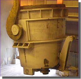 The use of infrared imaging is very important in the steel industry. One of these uses can be beneficial to the melt shop by viewing full ladles of molten steel. Once the scrap metal is melted in a melt furnace, the molten steel is poured into a large (175-ton ) ladle for transfer to the next operation. It is at this point, that the exterior of the ladle is scanned with an infrared camera. A ladle of hot molten steel ( 3100 deg. F) can go in a number of directions in the plant. With infrared, the exterior shell of the ladle can be scanned for possible “hot spots”. If the interior of the ladle, or brick lining, is worn or cracked, the molten steel can penetrate to the outside shell and burn through. Needless to say, this could be disastrous to nearby personnel and equipment. By detecting these “hot spots” early in the process, accidents can be avoided. The ladle can be diverted to a safe area and re-ladled into another ladle for transfer. Injury to personnel and equipment damage is avoided. The safety issue alone, is enough to justify the use of infrared imaging. If a ladle of steel is lost due to a breakout, the cost of that heat could run approximately $70,000.00 in lost finished product value. Equipment loss, near the breakout, could also run into the thousands of dollars. One breakout could cost a company well over the cost of an infrared camera that would help prevent such an incident.
Having mentioned the safety aspect of viewing hot molten steel ladles, there is another benefit that can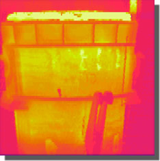 be realized by using infrared technology. After continuous viewing of the ladles over a period of time, the true life of the lining can be determined. At the present time, a ladle will see approximately (6) heats of steel in a 24-hour period. Before the use of infrared, a ladle would be scheduled for a re-line, with new brick, after about 35 to 40 heats. By continuously monitoring the ladle with infrared, the need to re-line a ladle may be extended past the 40-heat limit. If no exterior “hot spots” are being detected, the ladle can remain in service. With less re-lining required to maintain the safe operation of the ladle, large cost savings can be realized. The infrared image, shown at the right, was taken approximately ten minutes after the molten steel was poured into the ladle. This image shows some interior damage to the ladle lining, and is in need of a re-line real soon. The exterior surface is indicating “hot spots” around the middle area of the ladle. At this point, this is not a safe ladle to be using in the plant.
Steel Ingot
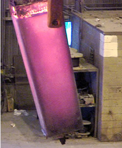 After the molten steel has been poured into smaller molds, called ingots, the steel can be furthered processed into bars by a rolling process. A single heat of steel can produce 24 ingots like the one shown in the image at the left. Each one of these ingots weighs approximately 13,750 lbs. It is at this point that infrared imaging can be used to scan the surface. It is important that the entire ingot be as close to uniform temperature as possible. These ingots need to be rolled at a pre-determined temperature in order for the proper dimensions to be maintained. The more evenly heated, prior to rolling, the better the finished product will be. Here again, the use of infrared is very beneficial.
By scanning the exterior surface of the ingot, just prior to the rolling process, will indicate how well and how evenly the ingot was pre-heated. The ingots are actually held in a heated bunker until its time for processing. These bunkers must maintain even heating of the ingots. A scan of the ingot will indicate any areas that are cool and may cause improper rolling into bars. When improper heating occurs, the heating zones in the bunkers may need adjustments to increase the temperature in one or more areas. If the infrared scans continue to show uneven heating, a re-design of the bunker may also 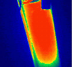 be required. The molds that are used to produce the ingots may also need re-designed. By going back one step in the process, it may be seen that too much heat is being lost after the molten steel is poured into the mold. By thickening up the corners and walls of the mold, the problem of lost heat is greatly reduced. An infrared scan of the surface of the mold will indicate any areas that are loosing heat. Once the heat loss is minimized, a constant monitoring of the ingots will prevent further rolling problems due to heat loss. An infrared image of an ingot, that is ready for processing, is shown below. There are some cooler areas near the corners, but generally, the ingot is fairly evenly heated. The molds and the heated bunkers are doing a good job maintaining an even temperature across the ingot surface.
Steel Bar Cooling Bed
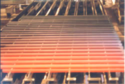
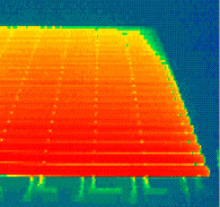
A major step in the production of steel bars, is the cooling process. Once the steel has made it to this point, the need to control the cooling process is very critical. Many of the steel properties are obtained during this stage of processing. Cooling rates must be developed in order to supply the customers with the exact steel properties that best suit their needs. To do this, the cooling process must be controlled by either slowing down or speeding up the cooling rate. There are a number of ways to accomplish this. The speed of the walking beam bed can be adjusted to move the steel slower or faster as needed. Air fans can also be used to blow cool air across the bed for faster cooling. Another technique that is used to cool the bars, is the spraying of a water mist over the entire surface of the bars. All these cooling methods can be manipulated to achieve the desired cooling rate. With the use of infrared imaging, the cooling process can be easily monitored. As can be seen in the above infrared image, the steel bars start out hot, at the bottom of the image, and slowly cool as they progress along the cooling bed toward the top of the image. At any point during the cooling process, a temperature profile can be obtained across the length of the bar to determine its temperature. Adjustments can then be made as to increasing the cooling rate or decreasing the cooling rate. Many heating and cooling processes have been established with the use of infrared technology. By storing the infrared imaging process on videotape, all newly developed heating or cooling processes can be kept for years and re-studied if needed at any time. All the temperature data is preserved along with all the images.
Induction Heating and Quenching
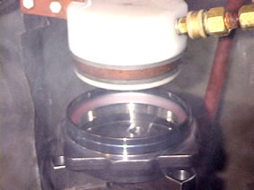
Induction heating and quenching are other processes that take place in a steel mill quite often. In this case, a steel bearing cup is being inductively heated to a temperature of approximately 1600 deg. F than quenched to achieve a certain hardness level. The following images show the cup just after it was inductively heated and the resulting infrared thermal image to the right. It can be seen in the infrared image that the inner raceway of the bearing cup is receiving the majority of the induction heating.
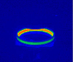
This is the area of the cup that will see the most wear and require the best hardening properties. The induction heating takes place fairly quickly and the duration of the quench is what dictates the development of the steel properties. In order to meet our customer’s specifications, the proper steel properties must be correct. The above bearing cup is used on cars and trucks and will be fitted with a sensor pack that controls anti-lock brakes. This application warrants good quality parts for safety. Any deviation in the customer’s specifications could have devastating results.
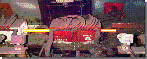
Here again, the use of infrared imaging can be used to check or monitor the induction process. With infrared, it can be determined if the process is heating the product to the proper level and how evenly this is taking place. The quench operation can also be monitored. Although not shown, another infrared image could be taken to show the amount of cooling that is taking place. From these images, adjustments can be made to the entire process to insure proper heating and cooling of these bearing cups. There are other induction heaters throughout the steel plant. A steel tube may need to be re-heated during a longer processing cycle to maintain its proper processing temperature. This tube can be passed though a heating coil to raise the temperature. An infrared image can be taken of this tube entering and exiting the coil. The picture below shows a hot tube entering and exiting the coil from the right. It can then be determined if the exit temperature is correct. Sometimes, correction to the coil power is required to increase the temperature. Once again, proper heating cycles can be monitored to insure accurate steel properties. The use of infrared thermography is very beneficial to controlling any heating or cooling cycle.
 |
 |
Bar Saw Cut Ends
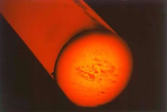
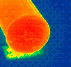
Sometimes it is beneficial to take a bar and actually cut it to view the interior. One reason for this would be to verify that the bar is evenly heated and to determine the actual core temperature. Images captured by an infrared camera only capture the radiated temperature of the surface of the bar. But, in the steel industry, it is necessary to know what the core temperature is. A bar that is processed at the wrong temperature can have bad effects on its internal properties. Therefore, with the use of infrared, the core temperature can be acquired very easily. The bar above has been cut, and an infrared image has been taken. A temperature profile across the bar will indicate how well the bar was heated and a maximum core temperature will be recorded. The difference between the core temperature and the surface temperature can be established. With this data, the core temperature can be calculated at any point in the cooling process just by knowing the surface temperature. This information is very beneficial because you can now control the proper heating or cooling cycle.
Steel Cut-off Saw Blades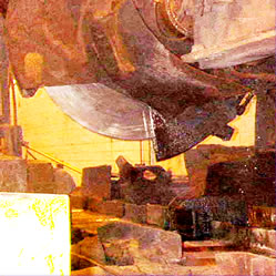
Shown to the right, is a picture of one of many steel cut-off saws that are located throughout the various plants. These saws are used to cut long lengths of steel product down to smaller sizes as it makes it way to the completion of the process. The need for small test samples are also required, and cut by these saws. Needless to say, the plant saws are used extensively and are very expensive to replace. An average saw blade could run approximately $500.00 each. It is critical to try to extend the life of these blades as much as possible. In the image to the right, the saw blade is exposed from beneath its housing. This is the area that does all the work and needs cooling water to prevent the blade from overheating. Infrared imaging was used to determine how hot the saw blades were actually getting. It is important that the blade be kept as cool as possible. A blade that is continually exposed to high temperatures will have a much shorter life. The infrared image, at left, was acquired just after the completion of a saw cut. Numerous tests were run to get a 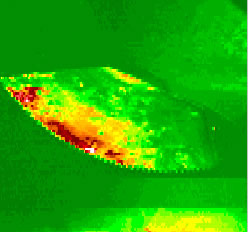 good average temperature of the saw blade near the teeth area. As can be seen, the hottest (red color) area is right at the critical teeth cutting area. With the use of infrared imaging, adjustments were made to the cooling water supply system. A different type of coolant was used as well as repositioning of the water lines that supplied water to the blade. These changes lowered the blade temperature and increased blade life significantly. The cost savings for the company was well worth the effort of an infrared scan.
Production Equipment Rolls
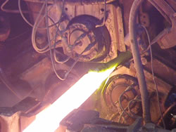 Processing equipment in a steel mill can get tremendous use and be subject to a great deal of wear. The rolls that are located inside certain pieces of equipment are used to form steel tubes, or bars, as it is being processed. This means steel to steel contact and generation of heat. Here again, as it was with the cutoff blades, it is important to keep the rolls as cool as possible. The image to the left shows a hot tube entering the process rolls on a reducing mill. The temperature of the steel at this point is approximately 1650 deg. F. The image at the right shows the same rolls after the passing of the steel tube. The outer surfaces of the rolls are continually exposed to high temperatures. These temperatures, if high enough, will cause cracking on the surface of the rolls. Once this cracking has taken place, the rolls will actually
 transfer the crack pattern to the steel being processed by the rolls. These crack patterns are then rolled into the surface of the steel
 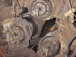 later on in subsequent processing. The rolls must then be turned on a lathe to remove the crack defects. There is a point where the rolls can no longer be repaired and must be replaced. With a large steel mill, the cost could be very high. In order to try to extend the life of these processing rolls, it is necessary to try to keep the roll temperatures at a level that will not create cracking at the surface to surface contact area. At left, an infrared image is shown of the roll surface that has been heated due to the processing of the steel. This heating is happening on all three process rolls in this equipment. The amount of heating is recorded with an infrared camera. If the temperature is determined excessive, it will be necessary for additional water to be supplied to this area of the rolls.The temperature must be lowered in order for surface cracking to be controlled. Once this has been achieved, greater cost savings can be realized due to less re-work and roll replacement.
Railroad Bearing Temperature Test
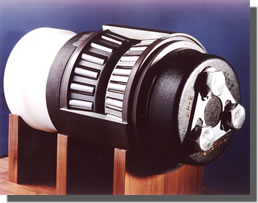
Pictured above is the Timken Company AP-2 Railroad Bearing. This bearing is used very extensively by the railroad industry on all types of rail cars. The AP (all-purpose) bearing was introduced to the market in 1954. The main attraction of this bearing was the fact that it permitted a simple conversion of existing railroad axles from plain bearings to tapered roller bearings. In the year 1958, it was determined that the 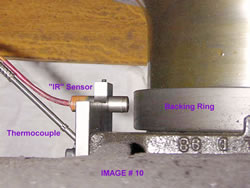 AP bearing brought annual savings to the railroad industry of about $288 million. In 1998, the AP bearing was subject to a temperature comparison test by a competitor. A large share of the railroad market was at stake. The test was set up to compare the heat being generated in the AP bearing vs. the heat being generated in a competitor’s bearing during actual railcar operations. “Rail Side Detectors” or “Hotboxes” were also used as a temperature comparison tool. A rail car was wired (see below) with infrared sensors on all eight wheels of the car. Four of the wheels had been fitted with the AP bearings; four of the wheels were fitted with competitor’s bearings. The IR sensors were placed in a position that detected the temperature of the bearing back plate. This was determined to be the best location to compare bearing temperatures.
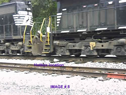
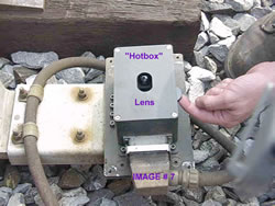
  This is also the location on the bearing that the Hotboxes see as the train is moving along the track. The image below shows the sensors as they were mounted on a bracket near the bearing back plate. Each one of these sensors will constantly read the bearing temperature during movement of the rail car. All the temperature data is stored in a data box onboard the train car for later analysis. As previously mentioned, the rail car passes over “Rail Side Detectors” or , “Hotboxes” approximately every 10 to 12 miles. These boxes also read the temperature of the bearings on each wheel of the car. These temperatures were also compared with the IR sensor readings. In the first image on the next page, you can see the location of a “hotbox” as it is installed near the tracks. The train passes over it and a temperature is sensed. A more close-up look can be seen in the next image. This shows the lens in the “hotbox” which opens and closes as the wheels pass by. The cost of these “hotboxes” run approximately $8,000 each. The main goal is to sense the temperature of the bearings and pass the information on to railroad controllers.
 |
 |
After all the IR sensors were mounted on the test rail car, it was put into service and run over a three- month period. At the completion of the three months, the data was downloaded and analyzed. All the temperatures were compared to each other and a report was issued. The AP bearings, once again, withstood the challenge and still proved to be the preferred bearing for the railroad industry. The main issue here is that different types of IR sensors can be used to achieve your goal. This was a good application in which to use infrared technology. Since 1998, the “hotboxes” are being slowly phased out. New “Generator” bearings are being installed on all railcars to supply power to every car. With there being power on every car, onboard IR sensors can be installed. There will be no need for Rail Side Detectors in the future.
Advertisement


