Adrian Messer
Manager of US Operations
UE Systems, Inc.
Ph: 864-224-4517Cell: 914-282-3504www.uesystems.comAbstract
Ultrasound and infrared technologies are a perfect match when conducting inspections of electrical equipment. At any voltage, thermal anomalies and sources of ultrasound such as tracking and arcing can occur. Corona can also occur at 1000 volts and greater. Any of these conditions threaten the reliability of the equipment being inspected.
Typical electrical components that can be inspected with ultrasound and infrared include switchgear, load interrupter switches, breakers, transformers, motor control centers, and terminal transition cabinets.
This presentation will provide information on how using both infrared and ultrasound together for electrical inspections can allow more problems to be found sooner, and also how safety is increased when using ultrasound to scan enclosed electrical gear prior to opening for further inspection. As a further complement to infrared inspections, sound file examples will be played in a spectrum analysis software to show how to properly diagnose electrical anomalies.
As a further complement to infrared inspections and to aid in the proper diagnosis of the condition heard, recorded ultrasound examples will be shown in both FFT and Time Wave Form from a spectrum analysis software to show how to properly diagnose electricalanomalies. This form of analysis is referred to as ultra sound imaging.
What is Ultrasound?
Hand-held airborne and structure-borne ultrasound instruments sense and receive high frequency sound waves that are produced from various sources that include turbulence such as a compressed air leak, friction as in an under lubricated bearing, and ionization in electrical discharges. These high frequency sounds are above the range of normal human hearing, and therefore cannot be heard in the audible range. The instrument receives the high frequency sound, and through a process called heterodyning, translates the high frequency sound into an audible sound heard through the headset y the inspector. The sound is then measured as a decibel (dB) on the display panel of the instrument.
Ultrasound is probably the most versatile of any PdM technology. Typical applications for ultrasound include compressed air & gas leak detection, bearings, motors, gearboxes, valves, steam traps, hydraulic applications, and for condition based lubrication of bearings and rotating equipment.
When it comes to electrical inspection, ultrasound instrumentation can be used on almost any energized electrical equipment including metal -clad switchgear, transformers, substations, relays, and motor control centers just to name a few. Ultrasound instruments can be used to inspect energized electrical components that are on low, medium, and high voltage systems.
Traditional inspection of energized electrical equipment has been performed by noncontact infrared cameras. However, in recent years, ultrasound instruments have been added to these inspections for various reasons. One of the main reasons has been safety. An ultrasound inspection of electrical equipment can be performed without opening the cabinet or enclosure.
Ultrasound and IR
One electrical anomaly that ultrasound will detect is corona. Even though corona produces little to no heat, it does produce ultrasonic emissions. If the inspector’s ultrasound instrument has on-board sound recording capability, the ultrasound emission from corona can be recorded and further analyzed for a correct diagnosis. A note of importance on corona is the fact that it is only present in voltage above 1000 volts. At 1000 volts and greater, air becomes a conductor and hence the ionization of air surrounding a connection can occur. If inspection is being done on voltages below 1000 volts, and an ultrasound is heard, the inspector can rule out corona as a possible diagnosis.
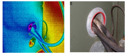
The images above show an infrared view and picture view
of obvious signs of destructive corona.
Corona typically does not show a significant delta-T with infrared.
Photos courtesy of Jim Brady
When the recorded ultrasound of corona is looked at in a spectrum analysis software, very prominent 60Hz harmonics can be noted. If the sound recording is done outside of North America, one would see very dominant 50Hz harmonics. Additionally, in between the 60Hz harmonics, you would see what is referred to as frequency content. Frequency content is basically harmonic activity between the more dominant harmonics. As the condition worsens, there will be a loss of the dominant 60Hz harmonics, and uniformity in the amplitude of the recorded ultrasound will decrease.

Recorded ultrasound of corona as seen in an FFT spectral view
Tracking occurs when there is a low current pathway to ground across an insulator. Many will refer to tracking as “baby-arcing.” This event is common where there is a severe breakdown of the insulating material and loose connections. Tracking can occur in low, mid, and high voltages and is characterized as a steady buzzing sound with periodic “crackling” and “popping” sounds. Further damage is done when tracking is not corrected, and will rather quickly lead to arcing.
The move from corona to tracking leads to a destructive path across the insulation, and creates pin-holes and spider web-like tracking which causes surface deterioration. When visually inspected, one can see a very obvious tracking path on the surrounding surfaces. Also, a conductive cloud of ionized air surrounds the connections. Flash-over can now occur once a tracking path is complete from phase to phase, or phase to ground.
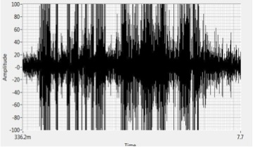
Tracking as seen in the time series view
Finally, arcing happens when there is a discharge to ground across an insulator. Arcing causes severe damage to equipment, plant/facility operations, and people. Melting of connectors, damage or loss of insulation, and fires usually result from electrical arcs. Arcing can easily be heard and detected with ultrasound. The sound characteristics for arcing are rather erratic bursts of discharges and popping sounds. These are identifiable when looking at a recorded ultrasound of arcing in the Time Wave Form.
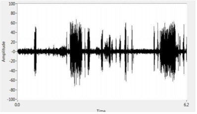
Arcing as seen in the Time Wave Form. Notice the lack of uniform harmonics
and the sudden starts and stops of the discharge.
Examples
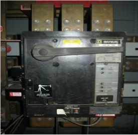
The image above is a 2000 amp main breaker. Arcing was detected on the B-phase line side. The arcing heard was worse when the load increased. The arcing has severely deteriorated the internal contacts, and eventually will become so deteriorated that the voltage and wave form will be unable to reach the load. At this particular facility, the replacement cost for this item is approximately $20,000 USD.
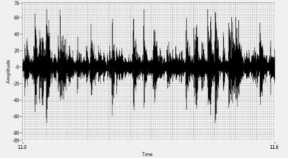
The Time Wave Form from the recorded ultrasound shows characteristic patterns
of arcing – changes in amplitude and a loss of well-defined 60Hz harmonics
The next example is from a 2000 KVA 11KV – 415v cast resin transformer. An inspection on this equipment was requested after audible noise in the area increased, so the operators knew something had changed for the area to become louder. The inspection was done during the winter months, and for this facility, this transformer typically sees a reduction in load as it supplies chillers and other associated plant equipment that normally does not work as hard during the winter months. During the inspection it was noted that the load was around 420 amps per phase.
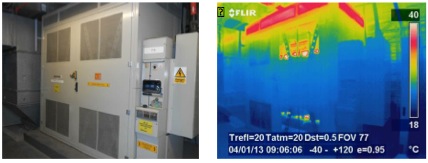
Images of the 2000KVA transformer
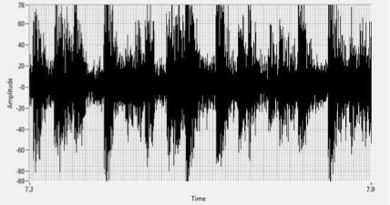
Time Wave Form of recorded ultrasound from this transformer showing characteristics of arcing
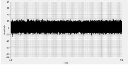
Time Wave Form of another 2000KVA transformer in the same facility showing
normal ultrasonic noise for this type of transformer
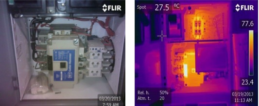
The next example is from a contactor on a piece of equipment called an orbit motor. A routine airborne ultrasound inspection was done, and distinct sounds of tracking were heard. A follow up inspection with infrared was performed, and the diagnosis was severe tracking.
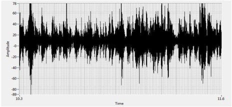
Time Wave Form view of the recorded ultrasound of this contactor shows
distinct signs of severe tracking and early stages of arcing
Conclusion
Ultrasound instruments are versatile and easy to use, and can greatly enhance inspections on almost any electrical equipment. In the end, it’s all about safety. Ultrasound inspections can be done prior to opening the energized gear to scan with infrared. If an ultrasonic emission is heard, then the proper precautions can be taken before opening the energized cabinet. Also, for those that rely on the services of an outside contractor to perform infrared scans, an ultrasound scan can be done in between the annual infrared scans to see if any emissions are heard.
When ultrasound and infrared are used together, an inspector is given a greater chance of detecting anomalies that could potentially be missed when relying on just one single technology. For best results, analyzing recorded ultrasounds in either the FFT, or time wave form view is the recommended method of diagnosing electrical anomalies heard with ultrasound.


