Lee Durston BS, CBST
Forensic Building Scientist
BCRA
2106 Pacific Avenue, Suite 300Tacoma, WA 98402253-627-4367www.bcradesign.com

Forensic Building Scientist
New standards in energy codes and contract requirements underscore a greater understanding of the importance of the continuous air barrier for commercial building performance. Recent studies have shown a sizeable energy savings in commercial buildings when the air barrier is designed, constructed, and tested with diligence. To substantiate performance of the completed building envelope relative to air leakage, a whole-house pressurization test to verify rate leakage and thermographic infrared imaging to locate problematic areas is recommended. Through multiple case studies, air barriers will be put to the test and discussion of construction strategies, performance, and testing methods will be presented.
Architects, contractors, engineers, and building owner-developers are beginning to see a new push to include air barrier systems into their structures. This has brought about numerous questions but very little in the way of answers. The International Energy Conservation Code (IECC) and several state energy codes – Massachusetts, Wisconsin and Michigan, with more expected to follow – now require the use of air barriers in all new construction. More important, energy efficiency and occupant comfort – two key ingredients of sustainable design – are driving the use of air barriers across a variety of market sectors. With today’s high cost of energy and concerns about Indoor Environmental Quality (IEQ), air barriers are one of several construction systems with a critical role to play. The form and function of an air barrier is not always well understood by many professionals – it is not a vapor barrier; at least not in all cases.
An Air Barrier is a system of building assemblies within the building enclosure – designed, installed, and integrated in such a manner as to stop the uncontrolled flow of air into and out of the building enclosure. Needless to say, air barrier system performance in the exterior walls, foundation, floors, and roof system are getting much more attention in the construction of high performance buildings. In fact, air-barrier systems in commercial/industrial buildings are estimated to reduce air leakage by up to 83 percent, save on gas bills by more than 40 percent, and cut down on electrical consumption as much as 25 percent, according to simulations by the National Institute of Standards and Technology (NIST). Although the results of this particular NIST study have not yet been field tested, the results are compelling.
Manufacturers and groups such as the Building Enclosure Council (BEC) have publicly confirmed the importance of air barriers to meet energy benchmarks and to building performance and sustainability in general. Without an effective, continuous air-barrier system, conditioned air tends to escape through the building envelope, and the heating, ventilation and air-conditioning (HVAC) system is forced to work harder to maintain the indoor environment. As the NIST report demonstrated, harder-working HVAC means higher energy bills. In fact, statistics from NIST and other academic and professional research groups have not only caught the attention of certain entities, such as the American Society of Heating, Refrigerating and Air-Conditioning Engineers (ASHRAE) and code officials in Massachusetts, Michigan and Wisconsin, they have led to new awareness of the fact that air barriers can also increase both the longevity and durability of the building envelope.
The uncontrolled movement of air into and out of a building can have numerous detrimental effects. With the growing global awareness of energy use, buildings are quickly being recognized as the low-hanging fruit for energy savings. The United States Department of Energy estimates that the operation of buildings accounts for roughly 40% of the nation’s energy expenditure, not including process loads within the buildings. The majority of this energy is used to condition the indoor environment. When creating the separation from the outdoors to this conditioned environment, one needs to construct a proper enclosure. The air barrier system is one component of this enclosure and works to stop air leakage. The three main forces causing envelope air leakage are:
Any one of these driving forces, or a combination of the three, can cause air leakage through cracks or gaps in the building envelope. Over the years, many strategies have been incorporated into the design and construction of buildings that have led to more energy efficient buildings, but the addition of a continuous air barrier to the building enclosure saves more than energy. In addition to combating energy loss through air leakage, the air barrier system works to improve the building enclosure by eliminating:
Air flow has the ability to transport an estimated 30 to 200 times more moisture into and through the building enclosure system than occurs through vapor diffusion. This is not to discount the value of a vapor retarder, which cannot be forgotten in lieu of an air barrier, but rather must be designed to work in harmony with one. The air barrier, unlike the vapor retarder can be located anywhere in the envelope assembly because its function is to stop air movement, not control diffusion. If it is placed on the predominantly warm, humid side (high vapor pressure side) of the enclosure, it can control diffusion as well, and would act as a low-perm vapor barrier, in which case, it is called an “air and vapor barrier”. Conversely, if placed on the predominantly cool, drier side (low vapor pressure side) of the wall, the air barrier should be vapor permeable (5-10 perms or greater). Today, building scientist’s work should be to create building systems that work properly, yielding both proper separation of interior and exterior spaces and alleviating premature degradation of the wall/roof system. Considering that walls and roofs account for approximately twenty-five percent of total building construction costs, bolstering the building envelope makes a lot of sense from the standpoint of both life cycle cost and building health.
The current push for energy conservation bears many similarities to that of the 1970’s oil crisis and the obvious strategy of tightening our building is as true today as it was then. What is often overlooked in both cases is that another strategy of increasing the R-value of our wall systems was incorporated. In the 1970’s many buildings suffered from adverse effects of energy conserving measures and this could potentially happen again today. In-wall condensation was a symptom of many failures in 1970’s era buildings and the cause is often misdiagnosed as the wall system being too tight and unable to breathe. In fact, in a heating climate, the addition of extra insulation had moved the dew point towards the interior side of the wall system.
When more insulation is added to the interior side of the wall system, less energy is lost through the wall and the dew point or condensation plane moves inward. The addition of a vapor retarder worked to offset this condensation by eliminating vapor diffusion, but the condensation caused by vapor-laden air leakage went unaccounted for. As the design and construction of today’s buildings requires greater insulation packages, we must be aware of the issues entailed in moving the dew point further inward in our building assemblies. Although strategies exist to negate this complication, e.g., including exterior insulation packages, none should be incorporated without a continuous air barrier system.
With this understanding, air leakage should never be considered as acceptable natural ventilation because it cannot be controlled or conditioned, and will not provide adequate or evenly-distributed ventilation. Ventilation of a building should rely on a design strategy based on the assumption that the envelope will be relatively airtight. The design of an air barrier system is complex and requires an in-depth understanding of building science principles if it is to be done effectively.
As air barriers in buildings are becoming more prevalent, many different strategies such as new materials and construction principles have begun to surface. As with all building materials and systems, time will weed out the concepts that don’t work or are non-constructible, and certain strategies will become the predominant design standard. Beyond that, certain factors are held to be true in the design of the air barrier system and should be met before the plans are stamped for construction. A list of requirements for any air barrier system are spelled out by the American Air Barrier Association (AABA). They include:
From a design perspective, the continuous air barrier must be included in the initial phases of the project to ensure the building is acceptable at delivery. With the multitude of project delivery methods at use in the industry today, the design-build sector is experiencing the largest volume of projects requiring continuous air barrier systems. This is due to the fact that the United States Army Corps of Engineers (USACE) and the United States Air Force (USAF) are now requiring continuous air barriers in both new construction and building renovations. In cases such as these, the continuous air barrier must be factored in as early as the submittal to the original RFP, be designed into an appropriate wall/roof/slab system, and be accurately priced. Upon selection, the knowledgeable design team must prepare plans and specifications that account for proper design and clearly translate the project’s needs and goals to the contractor performing the work. Plans need to be detailed in such a way to show the boundaries of the air barrier and specific details at all critical interfaces.
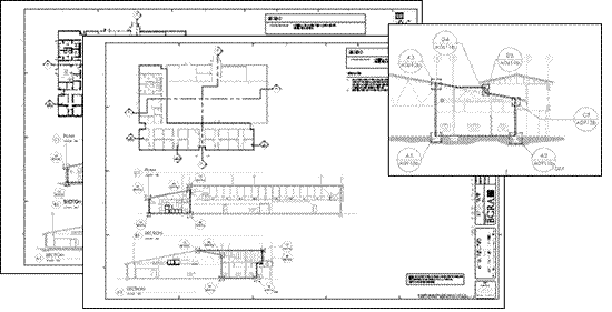
Figure 1. Plans showing detail and detail call-outs of the continuous air barrier
While some firms may not have expertise in the design of air barriers, they can sub-contract with other firms for this portion of the design process. Independent Technical Reviews (ITR) are typically completed at 65% and 95% submittals to ensure proper design.
With the design documents in place, the next step towards creation of a successful air barrier system is the construction phase services. Unfortunately, the standard of the industry does not currently construct in such a way as to ensure air tightness – regardless of what the design documents say. As we have found, this is not due to an unwillingness to perform work with integrity, but rather a communication breakdown between design team and contractor. It is essential to include for a briefing of goals and expectations at the pre-construction meeting. This may include the construction of a mock-up building section to familiarize the contractor with materials selected and the ways they are incorporated into the building enclosure.
Feedback from the contractor in this meeting often provides the design team with a greater understanding of the construction methods, and the collaboration towards solutions can be accomplished for even the most convoluted details. Throughout the construction phase, on-site observation by an air-barrier consultant is recommended. This provides for work to be observed for defects or errors, sample tests, the immediate answering of Requests-for-Information (RFI’s), and for an on-site representative to act as a liaison between the contractor and the materials manufacturer. This work is similar to that of a quality assurance engineer but specific enough to require an individual or group specialized in air barrier consulting.
Once construction of the building is complete, the performance of the air barrier system needs to be verified. Unlike other programs in the building community that support certifications through checklists or theory, this whole-building pressurization test is a representation of actual measurable conditions of a building’s performance. Much like water penetration testing, this testing gives a pass / fail result. Air leakage is measured as the rate of leakage per square foot of external envelope per minute at an artificial pressure differential through the envelope (cubic feet of air flow per minute per square foot of envelope).
The USACE has developed their criteria to allow no more air leakage than the equivalent of 0.25 cubic feet per minute with a pressure differential of 75 Pascals (0.03” w.c.). Two parameters are used: all wall, roof, and floor areas that are exposed to the external environment are included within the calculated area. Floor slabs in direct contact with the ground are included, as they are part of the enclosure.
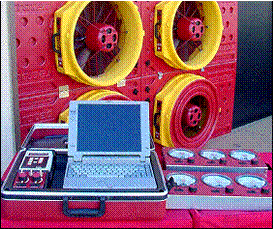
To establish a pressure gradient in order to measure air leakage the use of industrial blower door fans is incorporated. These fans can range in size from door units to large trailer mounted fans. Preparation for a test such as this is similar to that outlined in ASTM E779. All known penetrations that allow airflow into and out of the building envelope are sealed and the HVAC mechanical systems are turned off.
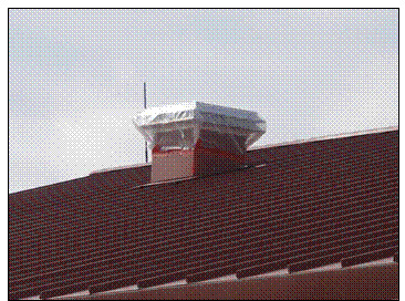
Figure 2. In preparation for an air pressurization test, the exhaust stacks are sealed off as they are understood to be a known or controlled air pathway
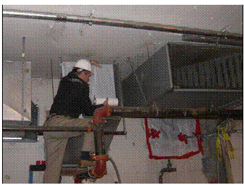
Figure 3. In renovation work, the sealing of existing ducting pathways needs to occur
Once this is complete, various measurements of wind speeds, temperatures, and pressures (both interior and exterior) are taken to help define any bias that may exist in the final results of the pressure test. The pressure test can then be completed in one of two ways: a single point test can be conducted by creating an interior/exterior pressure differential with the fan assembly and measuring the air leakage. The building can either be pressurized or depressurized to obtain this result, but the most accurate result is produced by averaging the two.
If the pressure differential defined by the requirement cannot be met with the fan power available, one can use a multi-point test. This allows for multiple data points of air leakage to be taken at various pressure gradients. By graphing the rate leakage as a function of pressure differential, the data can be extrapolated to determine a value for the appropriate testing pressure. When testing complex structures, it is recommended that all forms of testing be completed; both pressurization and depressurization of single and multi-point tests – the more data captured the more refined the final result can be.
 |
 |
|
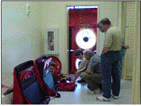
Figure 4. Large multi-fan computerized systems are used for larger facilities |
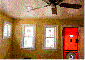
Figure 5. Single fan units can be used to pressure test residential properties |
 |
 |
|
Figure 6. Multi-fan systems make it easy to travel to test sites and set up in standard size doorways |
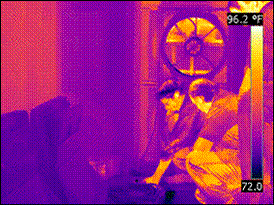
Figure 7. Corresponding infrared |
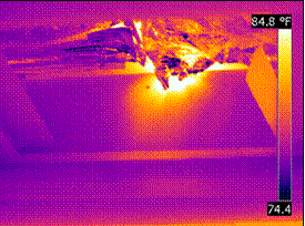
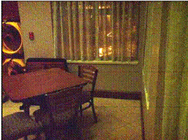
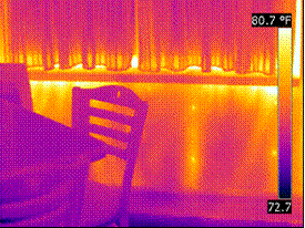
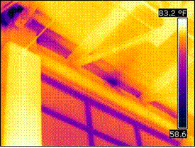
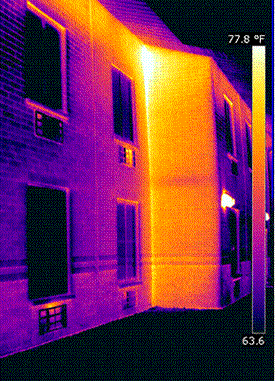
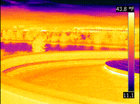
Whole building pressurization testing yields the overall leakage rate of the building and is accompanied by the use of infrared thermography to help visualize or locate actual leakage points and paths of travel through the enclosure. As the pressure differential is increased, any air leaking through the enclosure will most likely undergo a temperature change. Work prior to testing can involve heating or cooling of the interior spaces to exaggerate this temperature gradient. While infrared cannot see the leaking air itself, the surrounding building materials’ surface temperatures are affected by its flow, which can be easily detected by infrared.
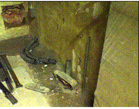
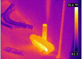
Figures 8 and 9 show that during depressurization testing, warm air from outside of the enclosure found a leakage pathway though an unused electrical conduit. Although the warm air cannot be seen with infrared thermography, the effects of the warm air are easy to visualize. The conduit and junction box are heating up and the air that is exiting the conduit stub upwards is warming the concrete wall directly behind it. This gives the investigator a definite leakage pathway to report with pictorial documentation to support the claim.
It is important to have infrared cameras with high resolution and high sensitivity to capture the narrow temperature gradients experienced. More importantly, it is imperative to have highly qualified infrared thermographers with building science thermography experience perform this testing. Thermographic air leakage patterns are often very subtle and diffuse, and without the proper equipment and personnel, air leakage pathways are easily missed.
 |
 |
|
Figure 8. Derelict conduit penetration in concrete slab |
Figure 9. Under depressurization, warm air can be seen entering into the space and presenting a thermal anomaly on the concrete wall behind |
 |
 |
|
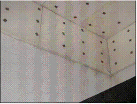
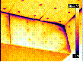
Figure 10. Insulation pinned to a below grade CMU wall |
Figure 11. Infrared thermogram taken while enclosure was depressurized. Air leakage in corner most likely due to settlement and/or cracking |
 |
 |
|
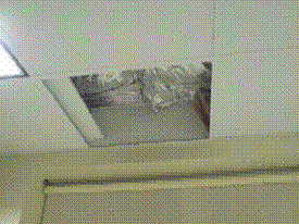
Figure 12. Removed drop-ceiling tile reveals foil faced insulation being used as the formal plane of building enclosure |
Figure 13. Infrared thermogram displaying warm air infiltrating from attic space while enclosure was under depressurization |
 |
 |
|
Figure 14. Window sill in a commercial facility |
Figure 15. Infrared thermogram reveals air leakage at window sill while enclosure is depressurized |
 |
 |
|
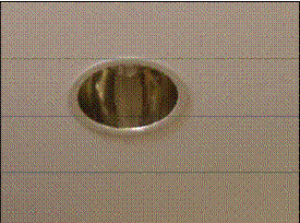
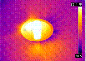
Figure 16. Recessed light penetrating the ceiling GWB that was intended to be the air barrier |
Figure 17. Infrared thermogram reveals air leakage around the recessed light while enclosure is depressurized |
 |
 |
|
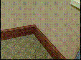
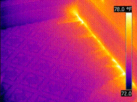
Figure 18. Base trim in a commercial facility with exterior wall on the right and interior wall across the top/left |
Figure 19. Infrared thermogram reveals air intrusion at base of wall while enclosure is depressurized |
 |
 |
|
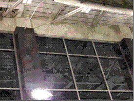
Figure 20. Curtain wall assembly as it interfaces with the roofing system |
Figure 21. Infrared thermogram reveals air intrusion at wall-to-roof connection while enclosure was depressurized |
 |
 |
|
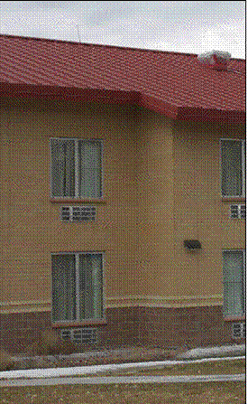
Figure 22. Exterior façade of commercial facility |
Figure 23. Infrared thermogram showing air leakage at inward corner while enclosure was pressurized |
 |
 |
|
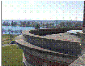
Figure 24. Roof detail on a historical renovation of a federal building |
Figure 25. Infrared thermogram reveals air leakage at the ballast roof to copper work interface while building was under pressurization |
 |
 |
|
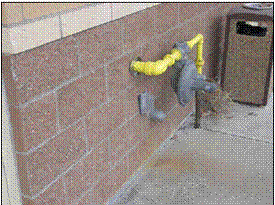
Figure 26. Electrical and gas utility penetrations in the enclosure |
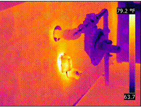
Figure 27. Infrared thermogram reveals air leakage at the electrical penetration while building was under pressurization |
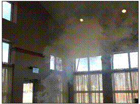
In addition to locating air leakage pathways with infrared thermography, techniques including smoke testing and invasive testing are also incorporated. Smoke machines, puffers or pens can be used to track the air currents.
 |
 |
|
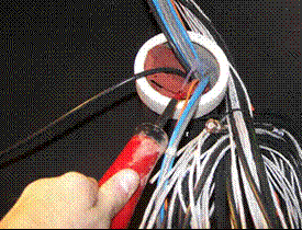
Figure 28. A theatrical smoke machine releases smoke inside the enclosure. When the building was pressurized the smoke could be tracked visually and was found to be exiting through the recessed lighting fixtures |
Figure 29. A smoke puffer is used to track air leakage through an audio/visual cable conduit, revealing a not so obvious short circuit for air leakage |
 |
 |
|
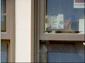
Figure 30. A smoke puffer is used to verify air leakage at a window assembly |
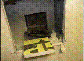
Figure 31. Invasive investigation reveals actual as-built conditions. Additionally, as each material is carefully excavated, a pressure differential can be measured between material planes which helps to understand the root cause of failure in a forensic investigation of an air barrier system |
As the requirement for a continuous air barrier is integrated into the building industry, there will be a steady learning curve experienced until projects are delivered at a high success rate. Very few firms exist in the US today that are ahead of this curve and can support the project by providing air barrier consulting services through all three phases (design, construction, and commissioning) of the building’s production. Typical design and construction methods implemented prior to this requirement need to change in order to realize successful projects.
Although energy costs have often been the deciding factor in the requirement of air barriers, it is a move in the right direction all around. Air leakage through the building envelope can lead to unnecessary heat loss in winter or heat gain in summer, condensation and moisture damage in hidden cavities, rain penetration, poor indoor temperature and humidity control, and excessive energy consumption.
As awareness increases, the air barrier will be specified more frequently in new construction and retro-active air-tightness measures on existing buildings. Qualified firms have developed multi-disciplinary services in effort to provide for the design, construction and testing of continuous air barriers in new construction and provide testing as well as remedial recommendations for existing construction.
Visit out Sponsors:
Electrophysics


Advertisement