John (Jack) N. Allinson, II BSc, AMS®
Level III Certified Infrared Thermographer
J.N. Allinson Associates, Inc.
Allinson Infrared Inspection Services, Inc.
222-2 University Blvd. NorthJacksonville, FL 32211Ph: 904-721-2177www.allinson.com
Abstract
More often than not, boats constructed with fiberglass reinforced plastic (FRP) and composite materials are damaged by lightning strikes, collision, and allision (moving boat striking a stationary object). In the insurance world of indemnifying the insured of a recreational yacht and/or small craft against loss, the extent of damage is often key in determining whether the boat can be economically repaired to pre-loss condition within the confines of policy coverage.
Defendable opinions of the cause, nature, and extent of damage are key items that an insurance claims adjuster needs to make decisions. More often than not a qualified Marine Surveyor can use non-destructive testing (NDT) as a means to provide those opinions to the insurance claims adjuster.
This presentation will provide pictorial examples of the types and extents of damages found by following the 2011 edition of the Infraspection Institute “Standard for Infrared Inspection of Recreational Yachts & Small Craft Constructed of Fiberglass Reinforced Plastic and Composite Materials”.
Introduction
Common to all damage marine survey reports prepared by J.N. Allinson Associates, Inc. are deliverables that provide a detailed and accurate description of:
- The unique identifying features of the vessel
- The site of the “Loss Event
- An opinion as to the overall condition of the vessel
- An opinion as to the estimated market value and replacement cost of the vessel based on a theoretical pre and observed post loss condition
- A list of “loss related” findings and recommendation to cure each finding
- An opinion as to an estimated cost of repairs needed to return the vessel to its
condition at time of loss
There are numerous types of Loss Events (e.g., smoke and fire, mechanical failure, electrical failure, wind storm, and submersion) and subsequent affected components survey (e.g., electrical vAC and vDC systems, navigation equipment, living accommodations) of a vessel to be examined during a damage. This paper will concentrate on how the use of infrared thermography can assist in addressing an evaluation of the structural integrity of a vessel’s FRP hull for the following three (3) types of loss events:
- a Collisionbetweentwo(2)vessels
- a LightningStrike
- an Allision, whereby a vessel strikes a stationary object
Structural Integrity
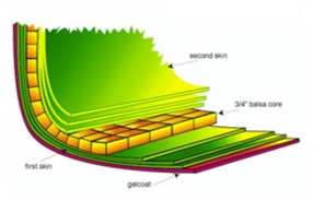
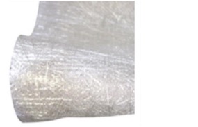
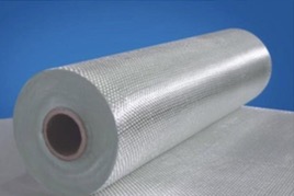
FRP vessel hulls may be constructed so that they are either primarily composed of layers of resin impregnated fibers (solid laminate) or resin impregnated fibers sandwiched around a core material (cored laminate). Fibers can either be of uniform lengths of bundled strands often referred to as a “chopped strand” or pressed together to make “chopped mat” or fiber strands that are woven or knitted into various cloth patterns. Three (3) predominant types of fibers are fiberglass, and cloths of carbon fiber or Kevlar®.
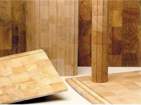
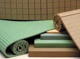
Core materials are usually either organic in nature such as marine plywood or end grain balsa wood, inorganic thermoplastic polypropylene, or aluminum honeycombs and closed cell PVC foams.
 |
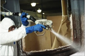 |
| Cross section of typical FRP hull with balsa wood used as the core material | GRACO chopper gun applying chopped strands of fiberglass while mixing with resin |
 |
 |
| Mat made of chopped strands of fiberglass |
Roll of woven strands of fiberglass |
 |
 |
|
End grain Balsa wood |
PVC Foam |
Types of Damage
Both solid and cored laminates share a common structural feature whereby they need to have the resin hold both fibers and core material in a fixed orientation. Structural failure of solid laminates show damage as either the resin releasing from the fiber or releasing the layers of cloth (delamination). Structural failure in cored laminates experiences delamination as well as a failure of the bond (disbonds) between the interface of the resin impregnated fibers and sandwich of core material.
Case Study: Collision 2008 Sunseeker 75 MY

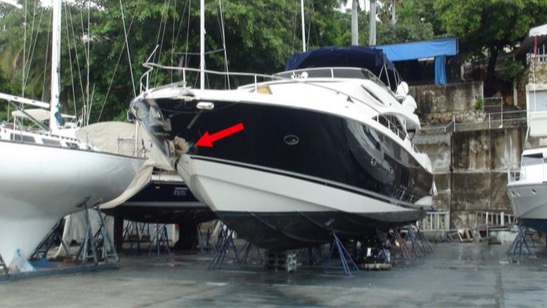
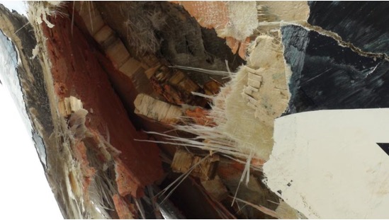
layers of fiberglass mat and cloth, bonding paste, balsa core, and layers of fiberglass cloth
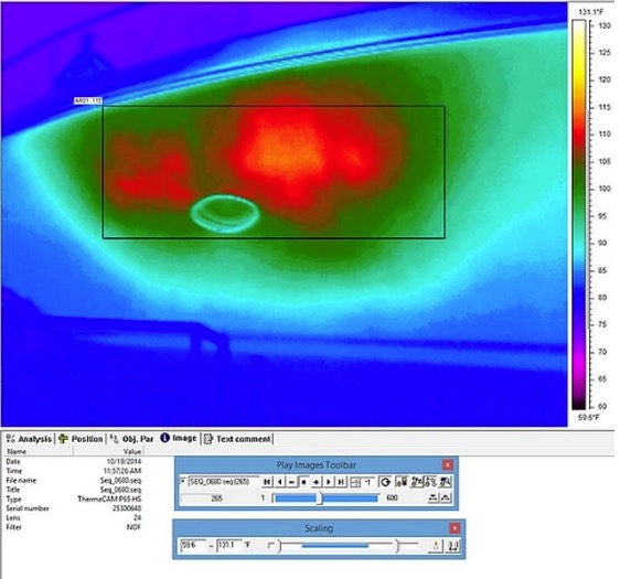
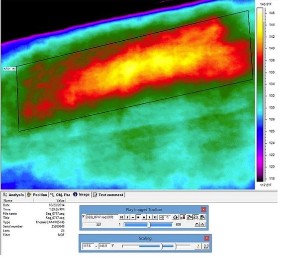
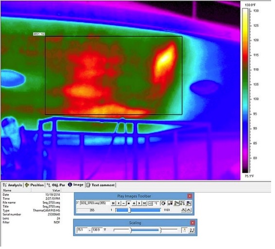
Case Study: Lightning Strike, 1998 Grady-White 232 Gulfstream
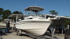 |
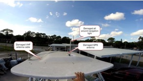 |
| Visual image shows subject vessel as stored on a boat trailer | Visual image shows hard top and evidence of entrance of lightning strike |
 |
 |
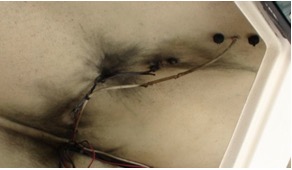
| Visual image of storage compartment beneath hardtop shows burnt electrical wires and evidence of lightning strike |
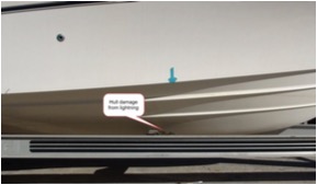
Visual image of STARBOARD exterior side of hull bottom shows location of lightning exit point |
 |
|
|
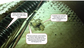
Visual image STARBOARD interior side of hull bottom shows location of lightning as it left electrical wires to the fiberglass hull |
 |
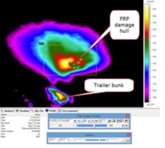 |
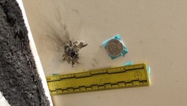
| Close up visual image STARBOARD exterior side showed size of burn mark on surface of fiberglass laminate from lightning exit point | IR image showed thermal anomalies in fiberglass laminate around lightning exit point |
 |
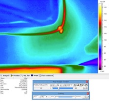 |
| Visual image shows burn mark on fiberglass laminate at junction between fiberglass laminate and extended aluminum transoms |
IR image did not show thermal anomalies in fiberglass at junction between fiberglass laminate and extended aluminum transom |
Case Study: Allision, 2001 Hunter 460 Grounding
 |
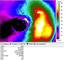 |
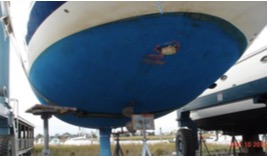
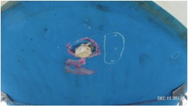
| Visual image shows where the rudder was sheared off the vessel, leaving a stub of the composite rudder post | IR image shows thermal anomalies on the exterior STARBOARD side of the fiberglass hull next to the rudder post |
 |
 |
| Visual image shows a chalk outline made of the thermal anomaly |
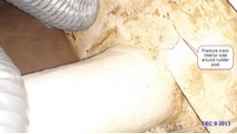
Visual image of interior side of fiberglass laminate surrounding the rudder post shows evidence of fracture cracks, corroborating thermal anomaly |
Conclusion
The deliverables of a damage evaluation are such that while a marine surveyor can learn how to apply IR as a means of damage assessment, it is more likely than not that an infrared thermographer will need to rely upon a marine surveyor to recommend the plan of action for implementing the study, interpret the infrared images and write the report of damage survey.
Refrences
DIAB GUIDE TO CORE AND SANDWICH – DIAB CORE GUIDE Revision 1 Issued December 2012
http://www.diabgroup.com
DIAB Group
Box 201
SE-312 22 Laholm, Sweden Phone: +46 (0)430 163 00
Fax: +46 (0)430 163 96
E-mail:
Standards
International Regulations for Preventing Collisions at Sea and/or the Navigation Rules: International – Inland – Obtain the Navigation Rules from the Superintendent of Documents, United States Government Information, POB 371954, Pittsburgh, PA 15250-7954.
ABYC – American Boat & Yacht Council July 2005, “Standards for and Technical Information Reports for Small Craft”, 3069 Solomon’s Island Road, Edgewater, MD 21037-1416
Allinson, II, John (Jack) N.; “Infrared Thermography in Marine Surveying” Technical Information Exchange for Marine Professionals, Vol. 19, No. 2 pp 4 & 12.
Allinson, II, John (Jack) N., J.N. Allinson Associates, Inc.; “Applying Infrared Imaging Techniques to Marine Surveying” InfraMation 2003 Proceedings September 2003 Volume 4, pp. 1-6
Allinson, II, John (Jack) N., J.N. Allinson Associates, Inc.; “Applying Infrared Imaging Techniques to Marine Surveying…continued” InfraMation 2004 Proceedings, October 2004 Volume 5, pp. 83-90
Allinson, II, John (Jack) N., Allinson Infrared Inspection Services (AIRIS), Inc.; “Infrared Imaging and the Detection of Great White Sharks and Cape Fur Seals” InfraMation 2004 Proceedings October 2004 Volume 5, pp. 83-90
CFR – Code of Federal Regulations and other government publications. Obtain from the Superintendent of Documents, United States Government Information, POB 371 954, Pittsburgh, PA 15250-7954.
NFPA – National Fire Protection Association, 1 Batterymarch Park, Quincy, MA 02269- 0901.
USCG – United States Coast Guard,
USCG Headquarters, Washington, DC, 25093-0001.
Various IR papers http://www.flirthermography.com/industries/industry/1027/


