Scott J. Nagle
Sales Manager / Application Specialist
Process Sensors Corporation
787 Susquehanna AvenueFranklin Lakes, NJ 07417201-485-8773www.ProcessSensorsIR.com
Abstract
Non-contact temperature measurement has long been used for industrial process monitoring and control. Although thermal imagers can provide more detailed information, their use in fixed process monitoring has been limited due to high cost and technological limitations. Recent advances combined with lower cost have made the use of fixed, high resolution thermal imaging systems a viable solution for a wide variety of process monitoring and control applications. This paper will address the use of thermal imaging for process monitoring and control, the state of current technology, installation considerations, and several application solutions.
Introduction
An emergence of new industrial process applications have surfaced for fixed process thermal imaging camera systems which never before was practical, due to the high cost and technological limitations of a thermal imaging camera’s detector array. Greater demand for thermal imaging detectors has accelerated research in developing new technologies for supplying a variety of detector array types.
The combination of higher demand and advancements in technology has fueled the increase in the number of detector array manufacturing companies worldwide. Fierce competition in this marketplace has resulted in reduced costs for these detectors, making it affordable to use thermal imaging camera systems in industrial process applications.
Discussion
Historically, it has been the prime domain of single point, non-contact infrared temperature sensors as the standard for use in industrial process temperature measurement applications. However, they posed many limitations and challenges in addressing the need to measure multiple spots or areas across the intended target.
It would take 76,800 individual infrared temperature sensors to measure the same area as one thermal imaging detector (UFPA) with an array size of 320 x 240 elements.
Realistically, it would take 8,533 single point IR sensors to make a comparable measurement to that of the aforementioned detector array because a 3 x 3 pixel area or a total of 9 pixels is needed to accurately make a true temperature measurement.
The clear advantage of a thermal imaging camera system is that it can monitor the distribution of temperatures over a wide area and be used for measurement and control of selected points or areas (ROI’s) on the observed target.
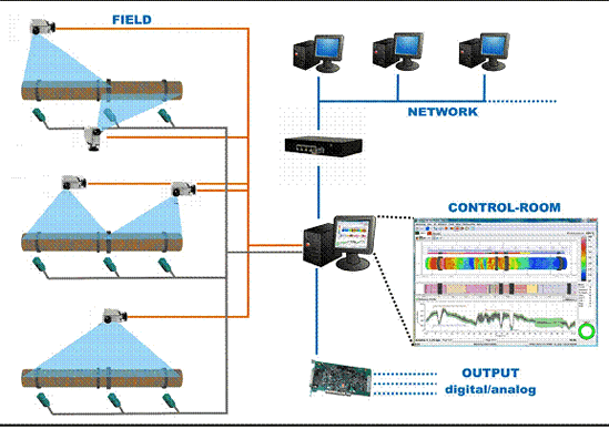
The components of such systems include a thermal imaging camera, a variety of lens choices, protective hardware, comprehensive software / integrated OPC & I/O modules for communication and control for direct interface to HMI’s & DCS systems. Additionally, they provide discrete 4-20ma analog outputs and relays for alarms.

Illustration of a basic system configuration for a fixed thermal imaging camera
One major component of a thermal imaging camera is the eye or UFPA detector that couples thousands of tiny detector elements onto a small semiconductor chip. The resolution of the detector array with lens combination determines the specific area and minimum measurable spot size at a distance for which the camera is applied.
Common UFPA detectors are offered in array sizes such as 160 x 120, 320 x 240 or 640 x 480 and are continually progressing to higher resolution levels.
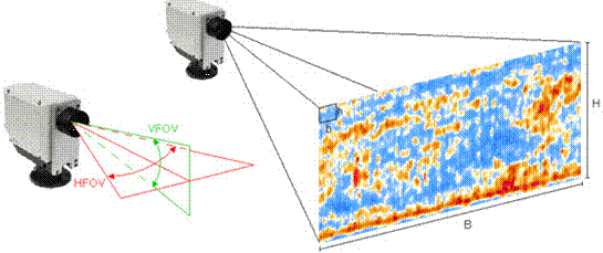
Use of a telephoto, close focus, or a standard lens assembly/attachments facilitate the angle of measurement or observed area (in degrees or radians) and is based on the type of detector resolution needed to resolve the minimum measurable spot within the overall observed field of view area.

Typical thermal imaging camera field of view diagram (FOV)
Prominent industries for use of thermal imaging camera systems include: steel, glass, food, thermoforming, rubber, cement, paper, power, petrochemical and many more.
Typical thermal imaging applications include:
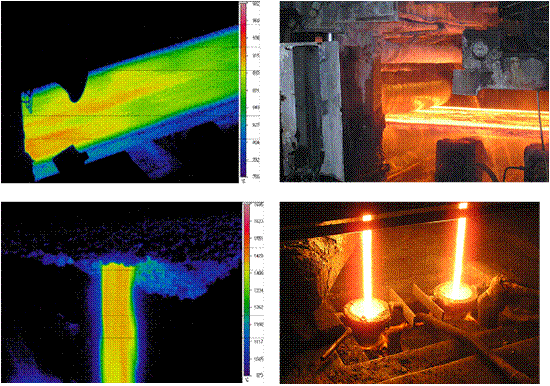
- Metals: molten pouring streams, ladle / torpedo car shells, continuous casting operations, fire prevention areas & heat treating
- Furnaces / Ovens / Heaters
- Tanks and Vessels (liquid level and refractory degradation)
- Boilers and Reactors
- Glass: molten glass, glass gobs, metal molds and tungsten filaments
- Semiconductor – Wafers, R&D Tool Design, Graphite heaters, crucibles
- Plastics Industry (Molding), Thermoforming Operations
- Pulp & Paper: rollers / equipment, paper, kilns – interior & shell, boilers
- Cement: kilns, clinkers on conveyor
- Critical process equipment; large motors / drives
- Furnace / vessel refractory degradation
- E-beam & Vacuum melting furnaces
- Research & Development

Process imaging applications of steel slab and pouring streams
As with any non-contact temperature measurement application, basic infrared guidelines must be followed to provide a unique and rock-solid solution. This resides on the shoulders of an experienced application sales engineer.
The bottom line in providing the best solution is to listen carefully and attentively to the customer about their requirements and most importantly, identify what their objective is to accomplish the task in hand.
Being able to physically see the operation of the process application is extremely beneficial to correctly interpret the application.
Based on infrared theory, visible light and infrared behave very similarly; they are reflected, absorbed, and transmitted. These components collectively contribute to what is termed as a product’s emissivity, a value and the ability to emit infrared energy. The higher a product’s emissivity, the more infrared energy it emits.
Conclusion
Review of an application can uncover many problems, such as seeing reflected high temperature IR energy (in the form of light) impinging on the target from an unwanted background source. The use of mechanical hardware, shielding or sighting techniques can be employed to eliminate erroneous temperature readings that can be caused by background reflections.
Also, considerations regarding the appropriate installation location can be determined based on the correct sighting angle and ambient temperature. In the case where ambient temperature exceeds the camera’s specification, the use of a water cooling jacket and air purge to keep the lens clean from debris is required.
Not until an application has been fully analyzed and the definition of the customer’s objective is realized, can a comprehensive solution be provided.
As manufacturing costs of detector arrays fall and thermal imaging camera systems become even more affordable, there will be a time in the near future that the well-established pyrometer will become a thing of the past.
Visit out Sponsors:
Electrophysics


