Level III Certified Infrared Thermographer
ASNT NDT Level III IR, MT, PT, UT & RT
Certified Welding Inspector (AWS CWI)
API 510 Certified Pressure Vessel Inspector
Owner, Senior Instructor / Managing Director
NDE Institute of Trinidad, Ltd. / Thermal Diagnostics Ltd. 15 Robertson Street, Les EffortsEast San Fernando, Trinidad & Tobago, West IndiesPh: 868-653-9343 / 868-657-6572www.learnndt.com
www.tdlir.com
Abstract
Knowing temperature accuracy of Reformer tubes and other critical heater tubes in chemical and petrochemical plants are of the utmost importance to all process and operation engineers. If temperatures are too low money is wasted from insufficient production. On the other hand, if temperatures are too high, tube life can be drastically reduced with the increased risk of costly and dangerous tube failures. In order to get the most effective use of reformer and critical heater tubes, temperatures must be kept as close to the maximum allowable temperature as possible. The industry rule of thumb is that a 20C° increase in temperature above its maximum allowable will halve the tube life. Therefore, being as accurate as possible in your field temperature measurements is a must for all plants.
This paper will discuss the common practical temperature measurement techniques used in plants to measure accurate tube temperature: Spot Infrared Pyrometer and Thermal Imagery. It will discuss how these technologies are commonly used by plant personnel with the error sources and limitations accompanied by them. A case study in the use of these techniques will be presented showing how current plant practices can result in considerable inaccuracies unbeknownst to plant personnel that can result in risky or unproductive operation adjustments.
Introduction
Primary steam reformers are used for the production of hydrogen. A hydrocarbon feedstock such as natural gas is mixed with steam and heated in the presence of a catalyst to produce crude hydrogen which is then purified.
Steam reforming takes place in a steam reformer furnace. The furnace is usually a large refractory lined box with gas burners heating many catalyst filled tubes that carry the feed (natural gas) and steam. Depending on the design, the reformer’s firebox or cell may contain only a single row of tubes or may contain multiple rows making it more difficult to obtain accurate temperature data (Figures 1 and 2).

Figure 1: Single Tube Row Reformer Figure 2: Multi Tube Row Reformer
Apart from the primary steam reformer, there are also several other critical types of furnaces in a chemical and petrochemical plant that require accurate tube temperature measurement. One such furnace is the ethane cracker furnace.
Both the primary steam reformer and ethane cracker furnace carry out a basic function in which they use a catalytic reaction to convert feedstock into a desired hydrocarbon fluid.
Another similarity is in the tube material used for these furnaces. Because of the elevated temperatures that usually are beyond that of a standard borne heater or reboiler, special alloy metals (HK-40, HP-MA, Et45-Micro) must be used in order to minimize the effect of creep damage and failure. Tube wall temperatures ranging from 700°C to 1200°C (1292°F to 2192°F) are common for these types of furnaces.
The temperature limits of these tubes are based primarily on the tube’s metallurgy (high Ni and Cr content) and the process. If the temperature is too high, then there is a real danger of creep damage and failure and the chances of coking increases, resulting in further tube metallurgical damage and process flow restriction. If the temperature is too low, then production output is decreased resulting in loss of profit in a highly competitive market.
If a plant is to get the most life out of their tubes while maximizing production, these tubes must be operated and fired as close to maximum operating temperature as possible. However, there is a real risk of exceeding this maximum operating temperature if accurate tube wall temperatures are not known. Industry rule of thumb states that a 20C° increase in temperature above its maximum allowable will halve the tube life and can result in costly and dangerous mistakes in tube temperature operation.
Temperature measurement of tubes is imperative for all reformers and critical heaters. Accuracy is critical but is it attainable? Plants may think they are accurate in their measurements but are they? How confident are they with their measured temperatures? Temperature accuracy is often disputed between departments (Operations, Production, Condition Monitoring, etc.); this is because it is very common to have all of these departments measuring the same tubes and acquiring different temperatures. Which temperatures are correct? Which are the most accurate? What safety margin should the plant use?
Current Commonly Used Tube Temperature Methods
In order to answer all the above concerns and questions, we must first understand the tools at our disposal to acquire temperature. Each tool or means of measuring tube wall temperature has limitations and error sources. Choosing the correct temperature measurement solution for any furnace will be dependent on these limitations, error sources and practicality.
The following are the two most commonly used methods for acquiring tube wall temperatures. We will discuss their basic principle along with the benefits and limitations:
Single Point Radiometer (Spot IR Pyrometer):
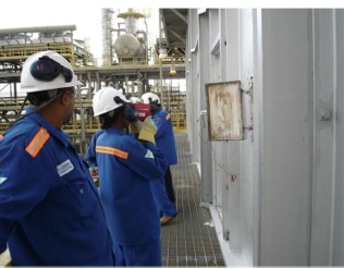
Single Point (Spot) Infrared Pyrometers are non-contact infrared measuring devices. They measure the amount of infrared energy that is emitted and reflected from the tube wall. The amount of infrared energy the instrument receives is then converted into a temperature reading. These units only measure a specific spot or area and do not provide imagery (Figure 3).
Benefits:
- Cost Effective
- Fast
- Simple to Use
- Repeatable Results
- Temperature Trending
Limitations:
- Frequently Used Improperly
- Spot Temperatures Only
- Spot Size (90:1 or 180:1). The Result is Increased Error Due to Distance
- No Diagnostics Ability
- No Reflected Temperature Input
- Accurate Tube Wall Temperature is Difficult
- Hot, Laborious Work
Although the Spot IR Pyrometer has many limitations, due to the simple use and repeatable temperature capabilities, this monitoring mode is well suited for the plant operator. Training on proper usage is important as these instruments in the hands of an untrained user will yield unacceptable inconsistencies and errors.
Thermal Imager / IR Camera (Portable):
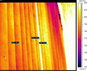
Portable Thermal Imagers (Infrared Cameras) are also non-contact infrared measuring devices and work under the same theory and physics as the Spot IR Pyrometers. However, Portable Thermal Imagers provide the advantage of imagery instead of only a spot. The added benefit of imagery allows everything in the field of view to be measured and the image can be saved for further computer analysis and historical data (Figure 4).
Benefits:
- Fast
- Identify Maximum Tube Wall Temperature Area
- Imagery of Tube Wall Temperature Profile
- Repeatable Results
- Temperature Trending
- Databasing of Imagery (Permanent Record)
- Problem Diagnostics Ability
- Most Adaptable to Tube Wall Temperature Accuracy
Limitations:
- High Cost
- Requires Advanced Skills
- Requires Proper Training in the Application
- Analysis and Reporting Takes Time and Skill
- Accurate Tube Wall Temperature is Difficult
Although Portable IR Imagery equipment or service is an expensive option, the data and diagnostics advantages exceeds all other forms of monitoring and makes it ideal for any furnace design. Training on infrared and the application is crucial. Having dedicated in- house personnel or qualified service providers is required. High degrees of skill and knowledge are required for this application to be of any use.
Overcoming Temperature Inaccuracies
The two most common methods for tube wall temperature monitoring discussed above have one major flaw: No Accurate Reference Temperature!
These two methods are essentially the same in that they both measure infrared energy from a distance with no contact with the tube wall. Considerable errors are introduced in the energy that is received by these instruments. In order to increase temperature accuracy with these instruments, these errors must be compensated for.
Proper field calibration is required in order to gain accuracy. All NDT methods that provide quantitative data require accurate calibration. The most accurate calibration requires calibration on same material, temperature, condition, etc.; therefore, the best calibration accuracy will be attained on an actual operating tube(s) in the furnace being surveyed.
There are other ways to quantify accuracy but these usually rely on a certain degree of assumptions and the use of default or estimated values. This may result in the inability to physically confirm actual accuracy. Physical confirmation of accuracy is ideal and recommended. So, in order to calibrate these non-contact instruments we must use a reference (calibration) standard.
What Reference Do We Use for Calibration?
There are several references that can be used. All have limitations that result in errors and uncertainties. None are absolutely perfect or accurate.
In order to gain the most accurate results from a reference, a method that provides the least limitations and errors for the application should be selected. By minimizing or even eliminating the significant error sources, accuracy will be increased.
The following are some methods used in the industry as a reference to calibrate non- contact infrared instruments for increased temperature accuracy:
Visual Color Comparison:
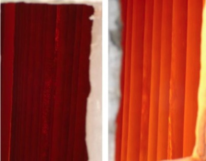
The theory behind Visual Color Comparison is that the tube wall will change in color at certain temperature limits. This change in visible color can be used as a means to quantify the tube wall temperature and adjust or calibrate the non-contact infrared instrument (Figure 5).
Benefits:
- Most Cost Effective
- Simple
- Visual Inspection is the First Line of Defense in Identifying Tube Problems
- Ideal for Flagging Changes
Limitations:
- Requires Skills & Experience
- No Actual Temperature Data
- Color Change is a Range – Not an Actual Temperature
- Tube Metallurgy Differs with Each Furnace thus Resulting in Different Visible Color Ranges
- Atmospheric Transparency or Opaqueness Affects Visibility
- The Range of Temperatures for Each Color Change May Exceed Acceptable Threshold Lomits
Embedded Thermocouples (Contact Tube Wall Temperatures):
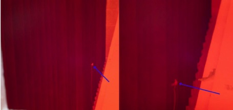
Highly accurate Thermocouples are either welded on the tube’s surface or embedded within the tube wall and connected to a reader or recorder. Thermocouples work under the basic concept of electromagnetic field differences between two dissimilar metals. This is then converted into a temperature reading (Figure 6).
Benefits:
- Low Cost
- Continuous Monitoring
- Simple to Use
- Repeatable Results
Limitations:
- Does Not Last Long in the Harsh Furnace Environment
- Does Not Measure Actual Tube Surface Temperature Due to Weld Mass or Embedment Within Tube
- Prone to Erroneous Readings
- Only Spot Temperature
- Must be Welded or Embedded on Tube
Reference Coupon / Specimen (Non-Contact Transfer Method):
A Reference Coupon is a fabricated probe made from an actual tube specimen that is inserted into the furnace to heat up. This probe has thermocouples attached to the surface of the tube specimen and a direct temperature is taken from this specimen when it reaches a stabilized or desired temperature within the furnace (Figures 7 and 8).
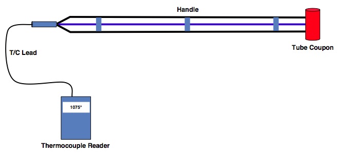
Diagram Courtesy Infraspection Institute

Image Courtesy Infraspection Institute
Benefits:
- Low Cost
- Reusable
- Simple to Use
- Repeatable Results
Limitations:
- Access May be Problematic for a Small Peephole Restricting Larger Diameter Tube Specimens
- Does Not Measure the Actual Tube in the Furnace
- Prone to Inaccurate Readings
- Only Spot Temperature
- Too Many Assumptions are Made (Temperature, Surface Condition, Emissivity)
- No Assurance that the Specimen will be the Same Temperature as the Actual Furnace Tube Because of Process Flow and Catalytic Reaction of the Furnace Tube. This Results in Emissivity Differences (Errors)
Gold Cup Pyrometer (Contact Tube Wall Temperature):
A Gold Cup Pyrometer is a Contact Infrared Spot Thermometer/Pyrometer that measures surface temperatures of objects by simulating a blackbody condition in order to eliminate errors from erroneous reflected temperature sources that would result in a larger error in temperature accuracy.
A Blackbody is simply a theoretical perfect emitter of infrared radiation. It does not exist in real life as all objects emit and reflect infrared light or radiation.
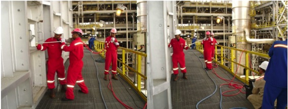
Reflected infrared radiation is a major source of error and leads to inaccuracies with all Infrared Pyrometers and Cameras. Even though the Gold Cup Pyrometer is an Infrared Pyrometer, it is designed to contact the furnace tube and block out the reflected infrared radiation, thus eliminating the major error source in temperature measurement via infrared thermometry (Figures 8, 9 and 10).
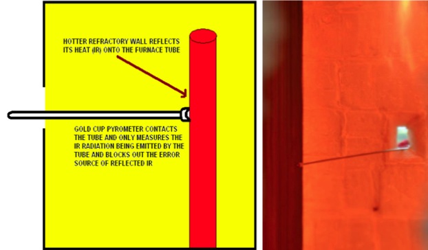
Figure 8: Sketch Showing How the Gold Cup Eliminates Reflected IR
Figure 9: Gold Cup Pyrometer Inserted Into Reformer to Contact Tube
Benefits:
- Fast
- The Most Accurate Physical Method of Measuring Tube Wall Temperatures
- Simple to Use
- Repeatable Results
- Cost Effective
Limitations:
- Length of Probe Limits the Distance that It can be Inserted Into the Furnace
- Heavy and Cumbersome to Maneuver
- Requires Several People to Support
- Only Spot Temperature
- Training is Required to Prevent Improper Use which Will Lead to Inaccuracies
Case Study – Temperature Accuracy of Infrared Technologies
This case study was performed in early 2014 on selected tubes of several ethane cracker furnaces at a refinery in the Middle East.
Debates between departments within the refinery as to who was obtaining accurate temperatures needed to be settled. Was it the operation, production or inspection department? Temperatures acquired on the same tubes at the same times were varying considerably. This had a direct impact and implication on the life of the tubes and the production outputs. The refinery would select the hottest tube on each furnace to measure and monitor in order to adjust and operate the furnaces within acceptable safety and production limits. This had a real, direct impact on safety and profit.
The operation and production departments use spot infrared pyrometers, while the inspection department uses a portable thermal imager.
All departments used default values to compensate for emissivity which was recommended by external consultant(s).
My services were contracted to design a means of settling the temperature accuracy debate and to come up with the best way to quantify the most accurate tube temperature for these furnaces.
For this specific application, a Gold Cup Pyrometer was found to be the most practical means of acquiring physical confirmation of tube wall temperatures.
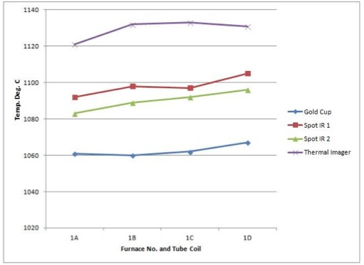
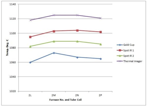
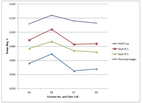
The following graphs are from three ethane cracker furnaces and show the temperatures of all methods used for this case study (Spot Infrared Pyrometers, Thermal Imager and Gold Cup Pyrometer) (Figures 11, 12 and 13):
From this case study exercise, the following results were concluded:
- The Gold Cup Pyrometer survey showed that the hottest tube of each heater was at a much lower temperature than what was being measured by all departments within the refinery and showed that they were incorrect in their assumptions of which department was yielding accurate temperatures (Figures 11, 12 and 13).
- The Gold Cup Pyrometer survey revealed the inaccuracies and deficiencies of how each department was using their non-contact infrared measuring devises (Figures 11, 12 and 13).
- The Gold Cup Pyrometer survey revealed that the plant can significantly increase production while still maintaining an agreed safety threshold.
- The survey revealed that using default values for calibration of equipment which was recommended by the external consultant yielded too much of a safety factor that inhibited maximizing production and affected profit significantly.
- The survey also revealed that there was an unacceptable difference between two identical spot infrared pyrometers and could be a result of calibration drift or improper use by the operator (Figures 11, 12 and 13).
This Gold Cup Pyrometer survey makes it possible for the refinery to critique and revise the current temperature measurement calibration and operating procedures for their non-contact infrared devices.
It also identified the need for proper retraining in order to yield a greater degree of accuracy to an acceptable limit for in-plant routine infrared surveys by all three departments.
It also allowed the refinery to increase production and remain within acceptable safety margins, thus increasing profitability and maximizing tube life.
Conclusion
Temperature accuracy of reformer and other critical furnace tubes is extremely challenging. It requires a firm understanding of the various temperature measuring methods and also of furnace and tube operation as well as metallurgy, failure mechanisms and other nondestructive testing methods. There are several factors that must be understood before taking on such a task: safety, cost, furnace design, operation, access, and equipment, just to name a few.
Acceptable and practical tube wall temperature accuracy is possible and achievable in the field. However, every project is different and may require a different approach. Training, knowledge, skill, experience, and attitude of the inspector performing this type of work are instrumental to temperature accuracy.
The instruments used are only tools. One should not assume that having the tools alone assures accuracy. Doing this would no doubt result in a false sense of security that would lead to considerable inaccuracies unbeknownst to plant personnel that might result in risky or unproductive operation adjustments.


 Sonny James