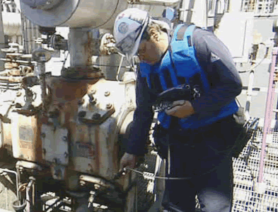
Ed Kochanek
Infrared Training Center
FLIR Systems, Inc.
25 Esquire RoadNorth Billerica, MA 01862
978-901-8000 www.flir.com/thermography/americas/us/
Abstract
Faulty equipment and poor maintenance practices often lead to excessive gas emissions that can result in lost revenue, environmental damage, regulatory fines, and compromised plant and public safety. Finding unknown leak sites allows for better preventive maintenance planning and repair, thus reducing overall tank emissions. This paper will discuss the latest infrared imaging technology which utilizes a special infrared detector and cold filter to help quickly visualize invisible gas leaks in real-time. We will also discuss how optical imaging can be used to aid in the detection and reduction of hydrocarbon gas emissions from storage tanks.
Regulatory Background
The Environmental Protection Agency (EPA) has mandated that facilities producing, using, or transporting volatile organic compounds (VOC’s) must continuously monitor their facilities for leaks. Most of these requirements are covered in federal publications 40 CFR, Parts 60, 61, 63, and 65. These publications consolidate and simplify the air quality rules that were originally part of the Synthetic Organic Chemical Manufacturing regulations. The goal is to significantly reduce the amount of VOC’s entering the atmosphere from a wide variety of potential leak sources, such as those depicted in Figure 1.
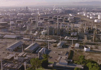
Figure 1. Petrochemical plants and tanks farms have thousands of potential leakage points
Discussion
The techniques for monitoring these leaks are contained in EPA Method 21, which is also known as Leak Detection and Repair (LDAR) methodology. In broad terms, the EPA recognizes the distinction between detection and quantitative measurement of leaks. In both https://irinfo.org/articleofmonth/images/s, the traditional method has been the use of flame ionization or photo ionization instruments, which are sensitive down to 10ppm or better. These instruments, referred to as toxic vapor analyzers (TVAs) or “sniffers”, use an algorithm that calculates a leak rate from the measured concentration. For high leak rates a “hi-flow sampler” may be needed. These instruments can measure gas flow rates up to about 10SCFM, and are usually calibrated in equivalent methane units.
Typically, a trained TVA operator can “sniff” about 500 components during an 8-hour work shift (see Figure 2). Since a large petrochemical facility can have hundreds of thousands of components that need to be monitored for leaks, TVAs generally require a large commitment in manpower and maintenance expense for LDAR. The EPA recognized the shortcomings of this approach to leak detection, and amended Method 21 with an Alternative Work Practice (AWP) The Alternative Work Practice to Detect Leaks from Equipment can be found on the EPA Website under 40 CFR Parts 60, 63, and 65. This AWP provides the option of using Optical Gas Imaging in lieu of sniffers for gas leak detection.
Figure 2. Toxic vapor analyzers (also called “sniffers”) are labor intensive, but can quantify the leak rate
Several state and local EPA organizations are also allowing optical imaging technology, which in some circles is being referred to as “Smart LDAR”. However, it’s important to recognize that most leaks are invisible to conventional digital camera detectors. Various ultraviolet (UV) and infrared optical imaging techniques have been tried with varying degrees of success in leak detection. A significant problem can be the wavelength at which a gas absorbs energy, as related to an instrument’s detection technology.
Principles of IR Imaging Technology
IR cameras have sensors that detect the difference in temperature between a target object or material and its surroundings (background). These sensors take the form of a focal plane array (FPA) of detector pixels. The camera lens focuses the infrared energy from a scene onto the FPA. The FPA output goes though a digital to analog (D/A) converter and calibration electronics that produce a visible image of the scene on the camera’s display, including temperature data. Camera firmware allows the user to display the image as either a gray or color scale representation.
Different detector materials are used to make an IR camera sensitive to specific portions of the IR spectrum, which covers a range of about 0.9µm to 14µm. For convenience, IR detector technology is described as Near IR (NIR), Midwave IR (MWIR), or Longwave IR (LWIR). Cameras using these technologies may also use narrow band filters to be even more selective in the portion of the IR spectrum that is detected.
IR cameras with microbolometer detectors have been used for years in preventative maintenance applications to detect temperature abnormalities in electrical and mechanical components. Since microbolometers are broadband IR sensors, they can detect a wide range of temperature anomalies that point to underlying problems in a component.
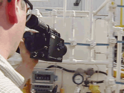
Figure 3. Typical usage of an IR camera for VOC leak detection
Detecting VOC gas leaks requires a different type of detector. The goal is to scan large areas with an IR camera and detect small leaks (Figure 3). These can then be inspected more closely with the camera and a quantitative measurement instrument. It has been found that many hydrocarbon VOCs absorb IR radiation in a narrow band of the MWIR region. For this, an Indium Antimonide (InSb) detector is used with a notch filter that restricts IR sensitivity to a range of 3.3µm – 3.4µm. Both the detector and the filter are cooled with a small Stirling cycle cooler to near-cryogenic temperatures to improve quantitative sensitivity.
Since a gas detection IR camera is a video device, the operator can see vapor motion caused by air currents in the vicinity of the leaking component. Individual video frames are stored in the camera’s solid-state memory, and can be extracted as still images (see Figure 4). In addition to saving video files, some cameras also have the ability to store individual “static” image frames to an SD card.
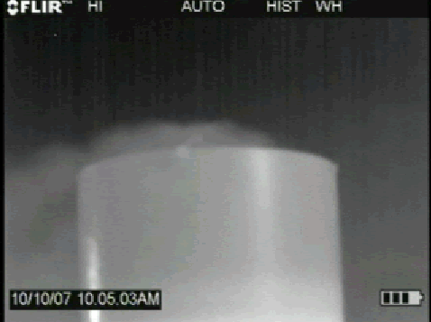
Figure 4. Storage tank leak caused by faulty vent valve
This methodology allows the detection of many hydrocarbon gases. A few of these are listed in Table 1. Some of these may require a LWIR camera and filter instead of using an MWIR camera and filter.
Table 1. Some hydrocarbon gases and leakage rates detectable with IR imaging technology.
| 1-Pentene, 5.6g/hr | MEK, 3.5g/hr | SF6, 0.026g/hr |
| Benzene, 3.5g/hr | Methane, 0.8g/hr | Toluene, 3.8g/hr |
| Butane, 0.4g/hr | Methanol, 3.8g/hr | Xylene, 1.9g/hr |
| Ethane, 0.6g/hr | MIBK, 2.1G/HR | |
| Ethanol, 0.7g/hr | Octane, 1.2g/hr | |
| Ethylene, 4.4g/hr | Pentane, 3.0g/hr | |
| Heptane, 1.8g/hr | Propane, 0.4g/hr | |
| Isoprene, 8.1g/hr | Propylene, 2/9g/hr | |
|
Other gases that can be detected (leakage rates to be determined) |
||
| Acetic Acid (C2H4O2) | Anhydrous Ammonia (NH3) | Butadiene (C4H6) |
| Carbon Monoxide (CO) | Chlorine Dioxide (ClO2) | Dichlorodifluoromethane (FREON-12: CCl2F2) |
| Ethyl Cyanoacrylate (Superglue: C6H7NO2) |
Many other gases that exhibit absorption at IR wavelengths can also be detected. | |
IR Usage Considerations
Up to this point, the focus of this paper has been on storage tanks and components in petrochemical plants. However, IR imaging technology can be applied to a large number of other applications. A few of these are pictured in Figure 5. The flare stack dump valve application (upper left in Figure 5) deserves additional comments.
Flare stacks are one way of reducing the amount of VOC emissions into the atmosphere. The EPA requires continuous monitoring of the stack to ensure that combustion has taken place to prevent unburned hydrocarbon emissions. As mentioned earlier, optical imaging is one way of monitoring the stack flame. Visible light cameras can work is some applications, but in others, the gas being burned renders the flame invisible. Furthermore, visible light cameras cannot see unburned gases that are exiting the stack. FLIR developed its GF Series cameras to detect both burning and unburned gases. When a stack flame is present, it shows up in the camera image as a higher temperature against a background of sky or clouds. There will also be an apparent temperature difference between unburned gases and the background. In either https://irinfo.org/articleofmonth/images/, the camera can output its data and images to a control room via USB communications and/or HDMI in the https://irinfo.org/articleofmonth/images/ of video images.
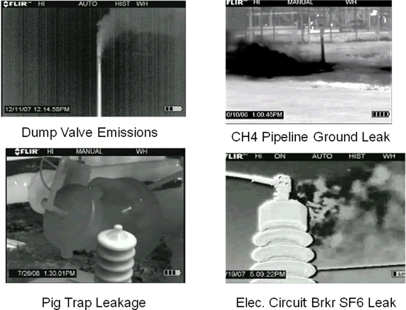
Figure 5. A few of the many applications served by IR cameras designed for gas detection.
Still, it’s important to recognize the necessary conditions that will allow IR imaging to detect fugitive gases. The primary conditions and qualifications for successful detection of gas leakage with an IR camera are listed in Table 2. These conditions are far from being restrictive. Like any other precision instrument, an IR camera must be used properly to take advantage of its full capabilities. It is often used as the first line of defense against fugitive emissions, and in conjunction with TVAs and/or hi-flow samplers to quantify the magnitude of a leak.
Table 2. Conditions and Qualifications for Successful Leak Detection with an IR Camera
|
|
|
|
|
|
|
|
|
|
Advantages and Benefits of IR Imaging
There are several advantages in the use of IR imaging technology for gas leak detection. IR cameras are lightweight, highly portable, robust instruments. For example, construction of the FLIR GF Series cameras is based on a design that is used in military field operations. Camera setup and use involves simple pushbutton operation. The FPA and filter used in a camera can detect a broad spectrum of gases. The camera displays real-time video images that make gas leaks more obvious. Individual video frames can be extracted as stills for use in reports.
In addition, there are several practical advantages to IR imaging in maintenance operations. An IR camera can be used to scan a large area of plant real estate as a first step in gas leak detection. This greatly shortens the process of finding individual leaks compared to the use of sniffers. IR scans are also much safer in that they minimize the use of ladders and exposure of maintenance personnel to toxic gases. Nevertheless, they can easily trace a leak directly to its source, providing a visual confirmation of exactly where it originates. Moreover, that visual image is stored in camera memory (i.e., built-in video recorder), creating a record of the leak and its subsequent repair. Some of these cameras also have an embedded GPS capability, which helps maintenance crews locate the component that needs repair.
These advantages lead to a number of economic benefits for companies adopting IR imaging technology. First and foremost, it finds more leaks and finds them quicker to reduce product loss and the risk of fires and explosions. Similarly, it reduces the chance of getting an EPA citation for emitting VOC’s into the atmosphere. Because it’s safer than many other leak detection technologies, the risk of OSHA citations is also reduced. When IR scans are incorporated into a predictive/preventative maintenance program, they make maintenance personnel more productive and lower costs. Reporting software and formal training in IR imaging technology can further increase its cost effectiveness.
About the Author
Ed Kochanek is Director of Sales for the Eastern Region of the U.S. for FLIR Systems, Inc., North Billerica, Massachusetts. His education includes a BS Degree in Commerce and Engineering from Drexel University, and he has over 10 years of experience in IR imaging technology.


