2010
January 04, 2010
Sponsored by:
![]()
IR Inspections of Parking Garage Ceilings
Tip Coauthored by Wayne Swirnow – Infrared Imaging Services
When inspecting building envelopes for heat loss, thermographers tend to focus their imaging efforts on the sidewalls and roof. For some buildings, it is important to also thermographically inspect the underside of the building.
In many parts of the United States a common building practice for commercial structures is to elevate the building on support columns and place an unheated parking garage directly below the first story. This practice exposes the underside of the first occupied level and its associated plumbing to the outside environment.
In colder regions a common approach is to construct a suspended ceiling for the garage and to create a heated space between the underside of the first occupied floor and the garage ceiling so that water, waste, and sprinkler pipes do not freeze. To minimize heat loss, batts of glass fiber insulation are often laid directly on top of the ceiling tiles.
When performed under proper conditions, an infrared inspection of the garage ceiling can quickly reveal thermal patterns caused by missing, misapplied, or damaged insulation. Areas exhibiting excess energy loss may then be visually inspected to ascertain cause.
Infrared inspection of building envelopes is of the many topics covered in the Infraspection Institute Level I Certified Infrared Thermographer® training course. For course information or to obtain a copy of the Standard for Infrared Inspection of Building Envelopes, visit Infraspection Institute online or call us at 609-239-4788.
January 11, 2010
Sponsored by:
![]()
Detecting Electrical System Overloads
Statistically, overloaded circuits are the second most common cause of exceptions found during infrared inspections of electrical systems. Although overloads are quite common, they can be tricky to accurately diagnose.
As electrical current flows through a conductor, heat is generated. As circuit load increases, so does the amount of heat. Electrical circuits are designed so that loads will not exceed the circuit’s ability to safely carry a sustained load and the amount of heat associated with such load.
Typically, overcurrent protection devices such as fuses or circuit breakers are designed to protect circuits from overload conditions. These devices will interrupt the circuit when the current reaches a predetermined level for a specified period of time.
Serious problems such as fires can be caused by sustained overloads. Such overloads may be caused by: improperly sized wiring, and improperly sized or defective overcurrent protection. Fortunately, a thermal imager can be used to detect the thermal patterns associated with sustained overloads.
When using a thermal imager to detect potential overloads, one should keep the following in mind:
- Overloaded conductor(s) will be uniformly warm throughout entire length
- For polyphase circuits, all conductors may be uniformly warm
- Depending upon ambient conditions and imager settings, overloaded circuits may not appear remarkably warmer than adjacent circuits
Because an infrared imager cannot measure electrical current, suspected overloads must be confirmed with an ammeter while observing all requisite safety precautions. For greatest accuracy, a true RMS sensing ammeter is recommended. Circuits found to be overloaded should be immediately investigated for cause and corrected.
January 18, 2010
Sponsored by:
![]()
Compensating for Reflected Temperature
When performing infrared temperature measurements, reflected infrared energy can be a significant error source. This potential error source can be overcome by using the proper radiometer and test procedure.
All thermographers have experienced reflected energy when inspecting low emittance targets. For qualitative imaging, single-point reflections may be avoided by changing viewing angle.
With quantitative imaging, failing to compensate for reflected energy can account for significant measurement errors. The infrared energy received by a radiometer is the sum of emitted, reflected and transmitted energy (E+R+T=1.0). For targets with a transmittance of zero, the error sources are emittance and reflectance. Using a quality radiometer, reflected energy can be measured and compensated for by using the Reflector Method described below.
1. Set radiometer Emittance control to 1.00
2. Locate radiometer at desired distance from target to be measured
3.Aim and focus imager
4. Position diffuse reflector in front of, and parallel to, face of target
5. Measure apparent temperature of reflector surface and remove reflector
6.Enter value obtained in Step 5 into radiometer’s computer under reflectance input – commonly labelled Background, TAmbient, or Reflected Temperature.
Lastly, be sure to maintain a safe working distance from any energized or potentially dangerous targets.
The topic of reflected temperature is covered in depth in the Infraspection Institue Level II Certified Infrared Thermographer training course. Copies of Infraspection Institute’s Standard for Measuring and Compensating for Reflected Temperature Using Infrared Imaging Radiometers are available in PDF format from the Infraspection Online Store.
January 25, 2010
Sponsored by:
![]()
How Delta T’s Understate Priorities
Tip written by: Infraspection Institute
For years, thermographers have traditionally reported apparent Delta T measurements when documenting their findings. Using a default emittance value between .8 and 1.0, apparent temperature measurements are recorded regardless of actual target emittance. While this methodology is fast and easy, it can lead to significantly understated Delta T repair priorities.
The temperature displayed by a radiometer is largely dependent upon the emittance and reflected temperature values entered into the radiometers computer. Typically, errors in either of these settings will cause temperature measurement errors that are exponential in nature and can cause large errors in reporting Delta T’s.
Example: Using an emittance value of 1.0 a thermographer measures the apparent Delta T between two, uninsulated electrical bus bars to be 44ºC. How much can observed temperature vary due to emittance values?
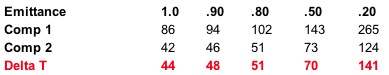
From the above, the following observations can be made:
- Emittance can have a significant impact on Delta T measurements
- The greater the variation between an object’s true emittance and radiometer settings, the more understated the Delta T
- Repair priorities may be significantly understated if accurate emittance values are not utilized
As there is no way to correct for errors introduced by apparent Delta T measurements, thermographers should utilize correct emittance values whenever possible. As always, all thermal anomalies detected during an infrared inspection should be investigated and proper corrective measures undertaken as soon as possible.
February 01, 2010
Sponsored by:
![]()
Understanding Imager Resolution
Tip written by: Infraspection Institute
Resolution is one of the most important objective specifications for a thermal imaging system. Due to a lack of standardization, this term is used in a variety of ways, many of which can be confusing or misleading.
Simply stated, resolution describes the capability of a thermal imager to clearly depict a target. Imager resolution is determined by an interdependent set of circumstances, the most important of which are described below.
- Detector: Some manufacturers offer total pixel count of the detector as a measure of resolution. Resolution generally increases with the number of pixels; however, pixel viewing angle (IFOV) also affects detector resolution. Meaningful IFOV data are frequently unavailable.
- Optics: Changing lenses affects an imager’s ability to clearly resolve a target at a given distance. Generally, telescopic lenses increase optical resolution; wide angle lenses decrease resolution.
- Signal-to-noise ratio: Generally, higher ratios equate to increased image resolution. Imagers with poor ratios will provide imagery that is grainy, thereby compromising image quality.
- Display Monitor: To maximize performance, the pixel count of an imager display monitor should equal, or exceed the number of detector pixels. Compact or monocular displays can severely limit resolution. Use of a high resolution monitor cannot compensate for low detector resolution.
When considering an imager for purchase, be certain to try the imager under the same circumstances that you will encounter in the future. Because there is no objective method to determine imager resolution, one should physically compare subject imagers to each other.
Infrared imager operation and maintenance are two of the many topics covered in the Infraspection Institute Level I Certified Infrared Thermographer® training course. For more information or to register for a course visit us online at www.infraspection.com or call us at 609-239-4788.
February 08, 2010
Sponsored by:
![]()
Contracts for Infrared Inspections
Tip written by: Infraspection Institute
A perpetual quest among professional thermographers involves seeking a standard contract for their inspection services. In this Tip, we offer a time-tested solution that can help to increase sales and improve customer satisfaction.
A contract is a binding legal agreement that is enforceable in a court of law. Simply put, a contract is an exchange of promises, which if broken, have remedy in the law. Among other things, an infrared inspection contract should address the responsibilities of the thermographer and the client, work to be performed, applicable standards and procedures, pricing, delivery, and payment terms.
Due to the diverse nature of infrared inspection services, preparing a one-size-fits-all contract can be very difficult. This challenge becomes even greater when ancillary services such as providing electricians or moisture verification are required as part of a project. In many areas, preparing a contract requires the assistance of a legal professional in order to ensure that the final contract meets all regulatory and legal requirements.
For professional thermographers, the first step in approaching any new project should be to generate a formal proposal. This proposal should contain all information pertinent to the project and be sufficiently detailed to reflect the responsibilities of all parties including the client and the thermographer. Once a proposal has been deemed satisfactory by a client, a Purchase Order or contract may then be prepared and forwarded to the thermographer for review and acceptance.
Infraspection Institute offers standard proposal templates for several different types of residential and commercial infrared inspections. Each template provides suggested wording and format for preparing a comprehensive and professional proposal.
Eight proposal templates are currently available covering the following applications: electrical systems, mechanical systems, electro/mechanical systems, building envelopes, insulated roofs, process equipment, steam traps, and underground piping. Each template outlines scope of work, pricing options, client and thermographer responsibilities, applicable standards, additional services, and terms.
All templates are provided in a Microsoft Word file and can be modified to suit the user’s particular needs. Templates may be used as core language for contract documents. Purchase price includes license for unlimited use of template by the original purchaser. Templates are available individually or as a complete set of eight through the Infraspection Online Store.
February 15, 2010
Sponsored by:
![]()
Calculating the Value of an Electrical Hotspot
What is the financial liability of a hotspot within an electrical system? Probably less than you think since electrical hotspots waste surprisingly little energy even when operating at high temperatures.
Over time, many have stated that the cost of infrared inspections can be justified through the detection and subsequent repair of hotspots associated with loose/deteriorated electrical connections. Although these types of defects can produce temperature rises of hundreds of degrees, the amount of energy wasted in the form of excess heat is often surprisingly small.
When detected in their formative stages, loose/deteriorated connections may contribute to only a few watts of energy loss. Even large temperature rises associated with significantly degraded connections will usually produce energy losses of less than 100 watts. We can calculate the financial impact of such an exception as follows:
0.1 kw x 24 hours = 2.4 kwh per day
876 kwh per year x $0.14 per kwh = $122.64 per year
It is important to note the above illustration is for an extreme hotspot operating undetected 24 hours per day for an entire year. While the above potential savings may seem significant, it would be hard to justify the expense of an infrared inspection program based upon energy savings alone. Justification would be even harder if the dissipated energy were only a few watts.
The real value of information obtained from infrared inspections comes from reducing unscheduled downtime, increasing reliability, improving safety, and avoiding losses associated with catastrophic failure.
Infrared inspection of power distribution systems is one of the many topics covered in the Level I Infraspection Institute Certified Infrared Thermographer® training course. For information on thermographer training or to obtain a copy of the Standard for Infrared Inspection of Electrical Systems & Rotating Equipment, visit us online at www.infraspection.com or call us at 609-239-4788.
February 22, 2010
Sponsored by:
![]()
Using a Blower Door During an IR Inspection
Tip written by: Infraspection Institute
Data obtained during infrared inspections can often be improved by incorporating other tools. When it comes to building inspections, a blower door can be useful in detecting air leakage sites and helping to gauge the airtightness of a building.
Air leakage is often a major source of energy loss in buildings. Although an infrared imager can help detect evidence of air leakage sites, it cannot pinpoint all air leakage sites nor can it quantify the amount of air leakage occurring. Many thermographers overcome these limitations by utilizing a blower door in conjunction with their infrared inspection.
A blower door consists of an instrumented, high volume fan that is temporarily placed in a doorway to create a positive or negative pressure within a building. In depressurized mode, the blower door simulates a wind blowing equally on all sides of the building. Conducting an infrared inspection with the building depressurized enables a thermographer to detect air leakage sites that would not be visible under natural conditions. With special software, it is possible to estimate the relative leakage of a structure as well as the total area of all leak sites.
A blower door can provide a thermographer with some advantages; however, there are challenges associated with their use. Using a blower door during an infrared inspection represents a “worst case” scenario and may not be indicative of natural conditions. This may invalidate thermal imagery that is destined for use in a legal case. Since blower doors can cause backdrafts from fireplaces, stoves, and heating equipment, they should be operated only by persons who are properly trained in their application and use.
Infrared inspection of building envelopes is one of the many topics covered in the Infraspection Institute Level I Certified Infrared Thermographer® training course. For more information or to register for a course, visit Infraspection Institute or call us at 609-239-4788.
Visit Infraspection Institute Web Site
![]()
Preventing Falls in Icy Weather
Tip provided by Conoco Phillips
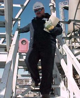
Numerous injuries result from slips and falls on icy sidewalks, parking lots, roads and other outdoor locations every year. Snow removal, sanding and salting of these type areas can help but, many times, total elimination of snow/ice hazards are impossible and other measures must be used to cope with these problems.
Focus on your walking path and pick steps that minimize or eliminate your exposure to icy slips. This is a time during which keeping your “eyes and mind on path” is more critical than ever.
![]() Accept and anticipate the fact that you are at risk of falling at any given moment when walking on ice. Adjust your stride so your center of gravity is maintained as directly above your feet as possible by taking shorter steps than usual.
Accept and anticipate the fact that you are at risk of falling at any given moment when walking on ice. Adjust your stride so your center of gravity is maintained as directly above your feet as possible by taking shorter steps than usual.
Don’t ignore the hazard presented by a slippery surface in your immediate path or work area. Take the time to spread sand, salt, or calcium chloride on icy areas and notify your Supervisor if further action is necessary. Keep in mind that salt (chloride) containing material is incompatible with stainless steel and is not to be used where contact can be made.
Footwear should have slip resistant soles. Avoid leather soled shoes. Equate this to driving a car with bald tires in the winter. You need something suitable to grip the surface you intend to walk on.
Wipe your feet off at the entrance of buildings so others won’t slip and fall on melted snow that has been tracked into the building.
 Like the ice under your feet, beware of icicles over your head; they can be dangerous. Although you cannot stop them from forming, you can minimize their effects by controllably knocking them down.
Whether you’re dealing with an overhead or underfoot ice hazard, if you can’t control it, barricade or rope the area off.
When walking down stairs with or without an item in one hand, Safety In Motion has a technique that can reduce your chance of falling down the stairs. Grasp the handrail in the palm up position trailing behind you instead of your direction of travel. Your feet should be positioned at a slight angle toward that railing. Should you loose your balance, your grip on the handrail in this position will cause you to come to a stop against the handrail instead of falling down the stairs. Try the technique and become comfortable with it before you need it. Make protecting yourself a top priority!
Visit Infraspection Institute Web Site
Infrared Inspection of Parallel Feed Conductors
Tip provided by Jim Brady – Brady Infrared Inspections, Inc.
Parallel conductors are a common feature on many electrical circuits. When properly used, an infrared imager can detect evidence of serious problems that might otherwise go undetected.
Insulated conductors play a vital role in electrical systems by carrying current to connected devices. Single phase circuits in receptacle and lighting panels use individual conductors to perform this function. Feeder type conductors however, are typically much larger in size and load carrying ability and quickly reach a point where it becomes impractical to install them using only one conductor per phase. In these cases, parallel conductors are used.
In theory, each parallel conductor should be the same diameter and length for a specified feeder circuit in order that the carried load is shared evenly among the conductors. Properly functioning parallel conductors on the same phase should exhibit equal temperatures with no discrete hotspots.
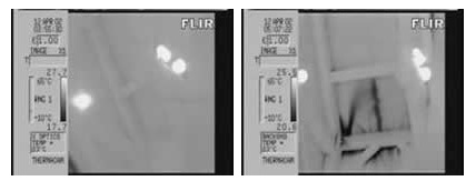
During a recent inspection at an industrial site, a 25 F degree temperature rise was observed on one of two, 400 amp rated parallel feed conductors that linked an 800 amp 3-phase breaker to the main lugs of a motor control center. An ampere reading showed that the warm conductor was carrying 450 amps while the paired conductor had less than 1 amp.
showing one cable 25 F degrees warmer than its pair.
An infrared inspection at the main lug compartment of the motor control center showed the same thermal relationship as observed at the main breaker and led to the discovery of a deteriorated connection that no longer was capable of carrying load. Under normal inspection protocol at this facility, this motor control center was not scheduled for infrared inspection for another year. If not for our investigation as to the cause of the thermal anomaly at the main breaker, this overload condition would have persisted and potentially caused a catastrophic failure.
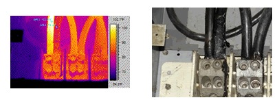
at the main lug of the motor control center.
When performing infrared inspections of parallel feed conductors it is important to understand that paired conductors are sharing load and therefore should have identical thermal patterns. Differing thermal patterns between paired conductors should always be investigated as overload conditions may develop on one or more conductors. Conductors operating at cooler temperatures are usually the result of broken conductors, conductors of drastically different resistance, or connections that have failed completely.
Visit Infraspection Institute Web Site
![]()
Do You Have the Correct Time?
Tip written by: Infraspection Institute
Most modern thermal imagers have the ability to record time and date along with thermal images. Taking a moment to ensure that the correct time and date are displayed on your imager before you begin your inspection can help to avoid wasted time and the collection of inaccurate data.
Having the correct time associated with your imagery is important for several reasons. With correctly dated imagery, it is possible to:
- Accurately document when the inspection was performed
- Easily store and uniquely reference image files
- Record the duration of a thermal event
It is always good practice to consciously check your imager’s clock each time you start your imager and make any necessary adjustments. Be certain to check your clock periodically during your inspection and whenever you restart your imager such as after a battery change or power interruption.
If your imager frequently displays incorrect time, it may be indicative of a defective or dead internal battery. To help avoid this problem, arrange for replacement of internal clock batteries whenever you have your imager serviced or repaired.
Infrared imager operation and use are two of the many topics covered in the Infraspection Institute Level I Certified Infrared Thermographer® training course. For more information or to register for a course visit us online at www.infraspection.com or call us at 609-239-4788.
Visit Infraspection Institute Web Site
![]()
Measurement Accuracy Specifications
Tip written by: Infraspection Institute
“A man’s got to know his limitations.” Clint Eastwood popularized this quote in a 1972 film; this sage observation can also be applied to infrared equipment.
When stating the potential accuracy of infrared thermometers, many manufacturers state radiometer accuracy as “± 2%”. The significance of this specification is often poorly understood causing many to overestimate the accuracy of non-contact temperature measurements.
An accuracy statement of “± 2%” is actually an abbreviated statement. The full statement is “± 2% of target temperature or 2º C, whichever is greater”. The full statement is required since measurement accuracy generally decreases with lower temperature targets. Furthermore, an accuracy of “± 2%” would place accuracy at 0% when measuring targets operating at 0º!
When considering an accuracy statement, it is also important to note that manufacturers derive accuracy specs under laboratory conditions using high-emittance, blackbody simulators in a controlled environment. As a result, manufacturers derive accuracy specs under “best case” conditions which may not be possible to duplicate in a given work environment.
To help ensure measurement accuracy, be certain to:
- Always measure perpendicular to target
- Correctly set radiometer inputs for emittance, reflected temperature, distance and humidity
- Ensure target size is adequate for subject radiometer’s spot measurement size
- Temporarily modifying low E targets can help to improve measurement accuracy
Lastly, real-world challenges can create situations where it is not possible to measure temperatures to the accuracy level promised by an instrument’s spec sheet. These challenges include, but are not limited to, hot or cold ambient temperatures, and the use of different lenses or filters. Whenever accurate infrared temperature measurement is not possible, one should consider using contact thermometry instead.
Infrared imager selection and operation are two of the many topics covered in the Level I Infraspection Institute Certified Infrared Thermographer® training course. For information on our open enrollment or Distance Learning courses, please visit us online at www.infraspection.com or call us at 609-239-4788.
![]()
An Emittance Greater Than 1.0 ?
According to the laws of physics, only a perfect blackbody may have Emittance of 1.0. Although the E value of real objects must be less than 1.0, some radiometers allow entry of E values exceeding 1.0. The following describes how these radiometers achieve the impossible.
Emittance is a measure of how well an object radiates energy when compared to a blackbody at the same wavelength and temperature. Emittance for any object is measured on a scale between 0 and 1.0. Since blackbodies (E=1.0) exist only in theory, real world objects will have E values of less than 1.0. The E value of an object can never exceed 1.0.
Assuming that most objects are opaque (T=0), they must be somewhat reflective. When making an infrared temperature measurement, this reflected energy represents an error source. To overcome errors due to reflections, quality radiometers have inputs for reflected temperature. By measuring reflected temperature and entering this value into the radiometer’s computer, this error source is compensated for in the radiometer’s software.
Less sophisticated radiometers often lack inputs for reflected temperature. To compensate for this, these radiometers allow the user to exceed E values of 1.0. Although this overcompensation may allow the user to match a desired reference temperature, it can lead to significant errors. For infrared temperature measurement, the best solution is to use quality radiometric equipment and eliminate or avoid reflections whenever possible.
Emittance and proper imager operation are two of the many topics covered in the Level I Infraspection Institute Certified Infrared Thermographer® training course. For information on our open enrollment or Distance Learning courses, please visit us online at www.infraspection.com or call us at 609-239-4788.
![]()
IR Inspections of Cool Roofs
Energy and environmental concerns have caused many facility owners to look to their roofing systems for ways to conserve energy. Modern roofing systems known as ‘cool roofs’ can provide savings; however, they can present challenges for thermographers who inspect them.
Over 90% of roofs in the United States are dark colored. On sunny days, temperatures of these roofs can reach 150º to 190º F causing decreased indoor comfort, increased cooling costs, and premature aging of roofing materials. Advances in roofing technology have led to the development of ‘cool roof’ systems that help to solve these challenges.
Cool roof materials have a high solar reflectance or albedo. Compared to conventional roof materials, cool roofs operate at lower temperatures since they absorb less energy from the Sun. Cool roofs also have a high thermal emittance enabling them to radiate well and shed heat quickly after sunset.
Cool roof membranes are usually made of single-ply rubber or plastic materials such as EPDM, PVC, and TPO. These materials are usually white in color and have a smooth surface. Cool roof coatings or paints are an alternative for existing low-slope roofs.
Although cool roof materials are rated to have a high emittance, thermographers should remember that this value is an average emittance value calculated in a laboratory under ideal conditions and at a perpendicular viewing angle. During an infrared inspection, smooth-surfaced roofs appear quite reflective to a thermal imager due to the low viewing angle that is usually associated with inspections performed on foot from the roof surface. This condition is most severe on cloudless nights when atmospheric humidity levels are low.
Due to the low emittance associated with smooth roof surfaces, thermographers can easily miss the small temperature differentials associated with latent moisture. In order to mitigate errors associated with low emittance, thermographers should choose a short wave (2 to 5.6 microns) thermal imager whenever inspecting a smooth-surfaced roof regardless of membrane color or material.
Infrared inspection of flat roofs and proper equipment selection are two of the many topics covered in the Infraspection Institute Level I Certified Infrared Thermographer® training course. For more information or to register for a course, visit Infraspection Institute or call us at 609-239-4788.
Visit Infraspection Institute Web Site
![]()
Spring is the Time for Infrared Roof Inspections
Tip written by: Infraspection Institute
With onset of warmer weather, the harshness of winter is but a fading memory for most. Left undetected, the damage caused by winter’s fury is a reality that can lead to premature roof failure. Fortunately, an infrared inspection of your roof can detect evidence of problems before they can get out of hand.
Performed under the proper conditions with the right equipment, an infrared inspection can detect evidence of latent moisture within the roofing system often before leaks become evident in the building.
The best candidates for infrared inspection are flat or low slope roofs where the insulation is located between the roof deck and the membrane and is in direct contact with the underside of the membrane. Applicable constructions are roofs with either smooth or gravel-surfaced, built-up or single-ply membranes. If gravel is present, it should be less than ½” in diameter and less than 1” thick.
For smooth-surfaced roofs, a short wave (2-5.6 µ) imager will provide more accurate results especially if the roof is painted with a reflective coating. All infrared data should be verified by a qualified roofing professional via core sampling or invasive moisture meter readings.
Infrared inspection of flat roofs and proper equipment selection are two of the many topics covered in the Infraspection Institute Level I Certified Infrared Thermographer® training course. For more information or to register for a course, visit Infraspection Institute or call us at 609-239-4788.
Visit Infraspection Institute Web Site
![]()
Insuring Equipment In Transit
Tip written by: Infraspection Institute
Shipping infrared equipment is a frequent necessity for thermographers. Taking the time to make certain that equipment is adequately insured can help prevent bigger problems in the event of loss or damage.
Many companies insure their infrared equipment to guard against loss or damage while the equipment is in use or transit by company employees. Typically referred to as Inland Marine or Scheduled Equipment, this coverage is generally purchased in addition to the contents portion of a company’s general insurance policy. In order to be covered, equipment must be specifically identified by make, model, serial number and value.
For those who find it necessary to ship equipment via a third party or common carrier, purchasing additional coverage known as ‘Goods in Transit’ may be a smart move. While many shipping companies offer options for ‘insurance’, such coverage is often quite limited and may be insufficient to properly guard against loss. In addition to providing better coverage, a Goods in Transit policy is usually less expensive than insurance offered by freight or parcel carriers.
Regardless of how you insure your equipment, be certain to review your policy with your insurance professional and understand exactly what is covered. Lastly, always make certain that equipment is covered for replacement cost rather than ‘Fair Market Value’.
Care and use of infrared equipment is one of the many topics covered in the Level I Infraspection Institute Certified Infrared Thermographer training course. For more information including course locations and dates, visit us online at infraspection.com.
Visit Infraspection Institute Web Site
![]()
What Do Thermometers Measure?
Tip written by: Infraspection Institute
When asked what a thermometer measures, most people will tell you that thermometers measure whatever they contact. The correct answer is a little more complex and is fundamental to understanding and accurately applying contact thermometry.
Contact thermometry is a common technique used in temperature measurement. Thermocouples, resistance temperature devices, thermistors, and bulb thermometers are used to gauge the temperature of a wide variety of objects, materials, and systems. Although each works on a different principle, all contact temperature devices have one thing in common: contact thermometers report their own temperature.
Because contact thermometry is often used by thermographers to confirm radiometric measurements and to calibrate infrared equipment, accuracy is extremely important. To help ensure accuracy when using a contact thermometer, keep the following in mind:
- Select thermometer appropriate for task. Be sure to consider sensor size, thermometer sensitivity, operating range, and response time
- Prior to use, confirm that chosen thermometer is calibrated and operating properly
- Make certain that selected thermometer is in good contact with object
- Allow sufficient time for thermometer to achieve thermal equilibrium with object
Prior to using a contact thermometer, make certain that the surface to be measured is safe to touch. Never use a contact thermometer on energized electrical equipment or on any machinery where contact could result in personal injury.
Advanced heat transfer and temperature measurement are some of the many topics covered in the Infraspection Institute Level II Certified Infrared Thermographer® training course. For course schedules or to register for a course, visit Infraspection Institute online or call us at 609-239-4788.
Visit Infraspection Institute Web Site
![]()
Determining Maximum Operating Temperature for Motors
Operating temperature can have a significant impact on the service life of operating electric motors. Accurately determining maximum operating temperature for motors is critical for setting temperature limits.
One of the specifications for electric motors is maximum operating temperature. This temperature value is determined by several factors including, but not limited to, the motor’s insulation class. Exceeding the maximum temperature for a motor will shorten the life of the motor’s dielectric materials and will result in decreased service life for the motor.
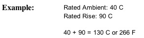
In order to calculate a motor’s maximum rated temperature, one must know the motor’s ambient temperature rating and its rated temperature rise above ambient. Both of these values are generally found on the motor nameplate located on the exterior of the motor casing.
To calculate a motor’s maximum operating temperature, add the ambient and rated rise temperatures. Their sum is the maximum operating temperature for the subject motor at 100% load.
It is important to note that some motors specify insulation class rather than a numeric value for temperature rise. In such cases, it is necessary to know the operating limits for the insulation class of the subject motor.
The Infraspection Institute Standard for Infrared Inspections of Electrical Systems & Rotating Equipment provides temperature limits for several common insulation classes of AC and DC motors. In addition to providing inspection procedures, it also provides temperature limit data for lubricants, bearings and seals. To order a copy of the Standard, call 609-239-4788 or visit the Infraspection online store.
Visit Infraspection Institute Web Site
![]()
Detecting Delamination of Stucco
With aging infrastructure becoming an increasing concern in many communities, more attention is being focused on the maintenance of building facades. Under the right conditions, thermal imaging can detect evidence of delaminated stucco or concrete finishes on the exterior of masonry buildings.
Over time, buildings that utilize concrete stucco for exterior finishes are subject to failure. One of these failures involves the stucco delaminating from its substrate. Delaminated stucco is a serious safety concern as it can cause serious injury to pedestrians should it fall from any significant height.
When concrete stucco delaminates from its substrate, an air pocket is formed between the stucco finish and the substrate. Because this air pocket acts as an insulator, it will change the thermal capacity and/or thermal conductivity in the area of the delamination. Under the correct weather conditions, thermal imaging can detect evidence of delaminated areas.
In order to detect evidence of delaminated areas using thermal imaging, a temperature differential must be present. Typically, infrared inspections of concrete stucco are performed during evening hours following a sunny day. As an alternative, infrared inspections may also be performed during midday under solar loading conditions. Thermal patterns associated with delaminated stucco will generally be amorphous in shape and will typically appear as cold spots during post-sunset inspections or as hot spots during midday inspections.
When performing infrared inspections of concrete stucco finishes, keep the following in mind:
- Subject surfaces should be clean and dry
- Wall surfaces must be heated uniformly. Areas in shadow or shade may not produce accurate data
- IR inspections are qualitative in nature. Compare similar areas to each other noting any inexplicable temperature differences
Once the infrared inspection has been completed, all thermal anomalies should be investigated for cause and appropriate corrective measures taken.
Infrared inspection of building envelopes is one of the many topics covered in the Infraspection Institute Level I Certified Infrared Thermographer® training course. For more information or to register for a course, visit Infraspection Institute or call us at 609-239-4788.
Visit Infraspection Institute Web Site
![]()
Detecting Defective Lighting Ballasts
Lighting ballast failure may present more than an inconvenience; in some cases, it may present a fire hazard. Under the right conditions, an infrared imager may be used to detect overheated ballasts.
Lighting ballasts are dry-type transformers commonly found within fluorescent and HID light fixtures. Because ballasts are usually direct-mounted to the interior of the fixture casing, surfaces adjacent to ballasts frequently operate at nearly the same temperature. In the case of fluorescent fixtures, ballasts are usually in direct contact with the top surface of the fixture.
Properly functioning ballasts will operate up to several degrees above ambient air temperature. Defects such as short circuits or defective wiring can cause a ballast to significantly overheat. If ballast temperatures are sufficiently high, a fire may result.
By using an infrared imager to inspect fixture surfaces adjacent to ballasts, it is possible to rapidly detect evidence of overheated ballasts. When applying thermal imaging to installed fixtures, keep the following in mind:
- Ascertain how construction of subject fixtures will affect observed temperatures
- Plan inspection to afford clear line-of-sight to fixture surface
- Ensure fixtures are properly lamped and under load during inspection
- Allow sufficient time for fixtures to achieve thermal equilibrium
- Investigate excessively warm fixtures for cause
Infrared inspection of electrical distribution systems is one of the many topics covered in the Level I Infraspection Institute Certified Infrared Thermographer® training course. For information on thermographer training or to obtain a copy of the Standard for Infrared Inspection of Electrical Systems & Rotating Equipment, visit us online at www.infraspection.com or call us at 609-239-4788.
![]()
Tornado Safety
Tip written by: Infraspection Institute
With the onset of warm weather, tornado season has arrived. In an average year, tornadoes in the US cause 80 fatalities and 1500 injuries. Knowing what to do before and during a tornado is crucial for survival.
Tornadoes are nature’s most violent storms. Spawned from powerful thunderstorms, tornadoes can cause fatalities and devastate a neighborhood in seconds. A tornado appears as a rotating, funnel-shaped cloud that extends from a thunderstorm to the ground with whirling winds that can reach 300 miles per hour. Damage paths can be in excess of one mile wide and 50 miles long. Every state is at some risk from this hazard.
Some tornadoes are clearly visible, while rain or nearby low-hanging clouds obscure others. Occasionally, tornadoes develop so rapidly that little, if any, advance warning is possible. The best defense against tornadoes is to be alert to weather conditions and be ready to seek shelter.
Before a tornado, be alert to changing weather conditions.
- Listen to NOAA Weather Radio or to local newscasts for the latest information
- Watch for approaching storms
- Know the danger signs: Dark, often greenish sky, Large hail, Large, dark, low-lying or rotating clouds
Loud roar, similar to a freight train
If you see an approaching tornado or are under a tornado WARNING, seek shelter immediately.
- If you are in a structure, go to a pre-designated shelter area or the center of an interior room on the lowest building level. Get under a sturdy table and use your arms to protect your head and neck. Do not open windows.
- If you are in a vehicle, get out immediately and go to the lowest floor of a sturdy, nearby building or a storm shelter. Mobile homes, even if tied down, offer little protection from tornadoes.
- If you are outside with no shelter, lie flat in a nearby ditch or depression and cover your head with your hands. Beware of flying debris and the potential for flooding.
For more information on tornadoes and tornado safety, visit the NOAA website.
Visit Infraspection Institute Web Site
![]()
Death by Blog
Tip written by:
Accolade Group
Do you like to tell everyone about your website? Do you take every opportunity to do so? Did you include it when you made the toast at your daughter’s wedding? Or, perhaps you slid it into your excuse when you were pulled over for speeding? Do you include it in every blog comment you make? Do you…. Wait! Go back!
What’s that abut blogs? Aren’t you SUPPOSED to mention your website, at least sometimes, when you make a blog entry? What if you’re visiting someone else’s blog and people are talking about something YOU do very well: shouldn’t you tell them that you can do whatever very well and shouldn’t you mention YOUR blog where they can see how great you are?
Well, yeah, all of the above are OK to do with the possible caveat that your daughter may never speak to you again. As for blogs, when you enter the URL that leads to your website some people may actually click on the link you’ve left and end up right where you want them: on your website. And that’s good, right? Yup, that’s good. That’s what you want.
Unless all you leave is a link to your website. That’s not so good. In fact, that’s bad. People who go around from blog to blog just entering the URL to their website are “blog comment spamming.” And, just so you know, a lot of people do that.
Search Engines in the old days, say, 2009, were once happy to see a URL to your website in a blog and include it in the Search Engine Result Pages (SERPS). But those who were only “blog comment spamming” put a swift end to all that. In fact, Google introduced “nofollow” link tags to put the “blog comment spammers” in their place. Thus, a link in a blog that leads to a website no longer carries the “juice” (really, that’s what it’s called) of the originating website that it once did. In fact, such links, thanks to the new Google tag, can have zero positive effect on Search Engines and may, to the contrary, have a negative effect on YOUR website. Oh, woe is me; what to do?
If you just have to link to your website from some blog, make sure that you write a nice, thoughtful, interesting comment to go along with it. If your comment is substantive and advances the argument (pro or con) that is being made by others in the blog or message board, it may well be picked up by the blog editor who, himself, will link to your website. Indeed, your comment may find its way into other online material where it is given a link to your website thus bringing the juice from that website via a Search Engine to your website.
So, the next time you feel compelled to comment with something like, “Hey, y’all, I talk about this stuff on my website at www.MyBigWebsite.com,” think how much better it would be if you offered something of substance with, of course, a link to your site.
Visit Infraspection Institute Web Site
![]()
Infrared Inspections of Retrofitted Roofs
If your roof has been retrofitted with a new roof installed over an existing one, it is imperative that you test the roofing system for water infiltration at least annually. With limited opportunity for egress, water entering the upper roof of a retrofitted system can cause widespread damage in a very short period of time. To make matters worse, there is usually no visual evidence of this type of a leak from inside of the building.
Performed in conjunction with regular visual inspections of your roof, infrared inspections of low slope roofs are a very cost effective way of tracking the overall health of your facility’s roofing system. Locating leaking areas while they are small allows them to be addressed before they can spread. Additionally, moisture trapped within a roofing system almost never dries out and can cause premature failure of the roofing membrane, adhesives, fasteners, and the roof deck.
Whether you choose to have an in-house thermography team or an outside contractor perform the inspection, make certain that the Thermographer is both Certified and experienced. Since an infrared imager cannot confirm moisture presence, all infrared data must be verified by invasive testing as well.
Infrared inspection of flat roofs is one of the many topics covered in the Infraspection Institute Level I Certified Infrared Thermographer® training course. For more information or to register for a course, visit Infraspection Institute or call us at 609-239-4788.
Visit Infraspection Institute Web Site
![]()
Begin With the End in Mind
“Begin with the end in mind” is a frequent quotation from Stephen Covey’s bestselling book, The 7 Habits of Highly Effective People. Applying this principle can have a dramatic impact on many things including an infrared inspection program.
Prior to underatking any task or project, it is important to have a clear understanding of what the final outcome should be. With this vision in mind, one is able to gauge the effectiveness of their efforts in achieving goals. By beginning with the end in mind, one knows what the goals are and can help chart a course of action that leads directy to these goals.
Building an infrared inspection program is like a construction project. You need to have a clear understanding of what you desire when construction is completed. When starting an infrared inspection program, decide what you want from your program. This is best done by asking yourself the following questions:
- What is the role of thermography – PPM, PdM, Q/A or Condition Assessment?
- Which systems/equipment do I want to inspect?
- How will thermorgraphy improve operations – decrease unscheduled downtime, improve product quality, reduce production losses?
- What data are available for measuring the program’s effectiveness?
Once these questions have been answered, one can begin to set up an infrared inspection program with necessary equipment, staff and support personnel. By beginning with the end in mind, an infrared inspection program is more likely to succeed by providing value and producing measureable results.
![]()
What Is a Subpoena Duces Tecum?
Tip provided by:
Robert J. Incollingo
416 Black Horse Pike
Glendora, NJ 08029
856-234-3800
www.rjilaw.com
A subpoena is a paper used in a court or administrative proceeding to command a nonparty to appear and testify, and in the case of a subpoena duces tecum, to produce certain items or documents for use in the case (sub poena = under punishment, and duces tecum = bring with you). Threat of punishment makes a subpoena a form of “compulsory process” by which the government exercises jurisdiction over you and your property.

A subpoena is not a summons; by contrast, a summons orders you to appear in court as a party to defend claims made against you. Failure to appear in response to a summons can result in entry of default and default judgment. Failure to appear in response to a subpoena can result in penalties for contempt of court.
So, you ignore a properly drawn and served subpoena at your peril, and the remedy of the requesting party will be to have you ordered to appear in court and show why you should not be held in contempt. The court or administrative tribunal in which the subpoena is issued will very likely be jealous of its authority in this regard. Fines and even incarceration are possible sanctions.
When served with a subpoena duces tecum, read it carefully, noting the date, time and place for appearance, and the material you have been ordered to produce. Then call your lawyer and send her a copy of the subpoena for review and appropriate comment. It may be that local custom allows you to send copies of the documents to be produced without the need for your appearance. If so, you will probably have to sign a certification which will enable the use of the records as evidence without formal foundational testimony.
If your testimony will be required at the court proceeding along with the subpoenaed documents, bring the originals. For certain evidentiary purposes, only originals will do. Ask your lawyer about local rules that apply to documents maintained in digital format – it may be that you can have the costs of production paid by the requesting party.
Remember, when served with a subpoena or subpoena duces tecum, you need to act with the advice of counsel. Ask your lawyer if the subpoena seeks your expert opinion testimony without lawfully required compensation. If the subpoena is defective or illegally intrusive or burdensome, your lawyer may move the issuing authority for an order to quash the subpoena, which is to say, a directive that the subpoena is null and void and of no legal effect.
Most times, a subpoena duces tecum merely requires the custodian of records to swear that documents produced were prepared and maintained in the ordinary course of business, and that entries in the records were made at or about the dates or times noted. Other times, the records are an afterthought, and witness testimony is the main event. At all times, a subpoena duces tecum is a serious matter, which if ignored or mishandled, can cost the careless recipient his money, his liberty or both.
Bob Incollingo is an attorney in private practice in New Jersey and a regular speaker at Infraspection Institute’s annual IR/INFO Conference.
![]()
Why Your Website Should be in a Directory
Tip Sponsored by: infraredprofessionals.com
Building a quality website is the first step in attracting new customers. Equally important is making it easy for prospects to find your site. In this Tip we discuss several key reasons for listing your site on a web directory.
Reason #1: You get better search placement when you join a directory
Search engines (even localized searches) heavily reward sites that have incoming links from other quality sites such as industry specific directories. The number of quality incoming links is the single most important factor in increasing your site’s visibility on any search engine results page.
By joining a quality directory, you are effectively paying them to promote you and to link to your site. The more links to your site, the higher you will be listed in search results, the higher you are listed, the more likely prospects will find you and use your services.
Joining one or more quality directories is the most cost effective way to improve your site’s rankings, and that is why directories are still so popular.
Reason #2: Customers want choices with no commitment
Unlike quote generators (sites that ask you to provide an email address and promise to have “qualified” companies in your area contact you at a later date), quality directories do not require personal customer information before they display company listings.
No one likes to get spammed when searching for a new product or service, and that is why directories are very popular. By joining a quality directory, your company increases its chances of being found and contacted by privacy conscious consumers.
Reason #3: Safer for the customer
Today, customers are very cautious when visiting new websites due to increasing security concerns. The number of smaller websites affected with malicious code (malware) is increasing, and many websites don’t even know they have been infected. For instance, in 2009 Google found more than 350,000 sites that had malware and the number of sites are expected to continue to increase.
Internet directories link directly to your site, instantly giving your site credibility. Quality internet directories also constantly monitor their company profiles to prevent spam or dangerous sites from being listed. Customers find this “filtering” to be much safer than simply clicking on search results with the risk of exposing themselves to an unknown site.
Of course not all consumers are this security minded. But for the significant number that are, joining a directory may be the only way that you will get to present your services to them.
Infrared Professionals.com is the largest infrared inspection company directory on the web. For a limited time, we are offering a free 12 month listing (a $179 value) for infrared inspection companies. For more information, call 877-994-7776 or visit us online at www.infraredprofessionals.com.