2005
![]()
Four Steps to Solving Problems
Solving problems is a constant challenge for most managers. The effectiveness of a manager is directly tied to their ability to accurately define a problem and find the most effective solution. This week’s Tip discusses a simple and proven method for solving even the toughest problems.
Like any project, problem solving involves a series of steps. When completed, the following simple steps should provide an effective solution to nearly any problem. Be certain to complete the steps in order before advancing to the next step.
Step 1: Define the Problem. This is often the most difficult part of solving any problem. Without an accurate problem definition, we cannot begin to find an appropriate solution. When defining a problem, keep it simple and direct, limiting your description to 10 words or less. Once you are certain that your problem definition is accurate, proceed to Step 2.
Step 2: Outline Possible Solutions. Make a list of all possible solutions to the problem you’ve defined. Feel free to brainstorm and let your imagination run free. This is a step for gathering ideas – not for being critical. When appropriate, be sure to seek the input of others.
Step 3: Determine the Best Solution. Drawing from the list generated in Step 2, select the best possible solution to the problem.
Step 4: Implement Your Best Solution. Be sure to monitor the problem and your implemented solution for its effectiveness. If your chosen solution is ineffective, return to Step 3 for an alternate idea.
![]()
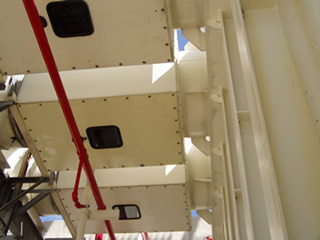
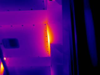
Infrared Inspection of Ballasted Roofing Systems
Infrared inspections can help to detect latent moisture within smooth or gravel-surfaced insulated roofing systems. For roofs covered with high-density ballast or pavers, other forms of non-destructive testing such as capacitance or nuclear gauge testing may provide better results.
For infrared inspections performed during post-sunset hours from the exterior of a building, the collection of accurate infrared data is highly dependent upon roof construction. Applicable roof construction is as follows: Built-up or single-ply membrane installed over, and in continuous contact with, a layer of insulation or an insulating deck. Roof may be smooth, granule-surfaced or gravel-surfaced. If gravel-surfaced, stones should be pea sized or smaller with a thickness of less than one inch.
Roofs covered with concrete pavers or river washed ballast (walnut-sized or larger rock) are not candidates for an accurate infrared inspection. In general, the presence of ballast materials will mask the small temperature differentials associated with latent moisture since they are capable of absorbing large amounts of solar energy during daylight hours.
For some ballasted roofs, it may be possible to detect limited thermal patterns associated with latent moisture; however, this is highly dependent upon roof construction, ballast thickness and density, and local weather conditions. In most cases, the presence of ballast will prevent a thermographer from accurately detecting thermal patterns associated with latent moisture.
For ballasted roofs, it is often prudent to utilize either a capacitance or nuclear gauge instead of thermal imaging. In the hands of a competent technician, these technologies will usually provide more accurate data for detecting evidence of latent moisture within ballasted roofing systems.
![]()
Understanding Electrical Arc Flash
According to the National Fire Protection Association (NFPA), an arc flash is “a dangerous condition associated with the release of energy caused by an electric arc.” Explosions associated with arc flash can cause severe burns, injuries and/or death. Understanding arc flash is the first step to guarding against it.
Often, the most serious injuries associated with electrical accidents are caused by the effects of arc flash, not electrocution. When an arc flash occurs, tremendous amounts of energy are instantaneously released creating the potential for serious or fatal injuries. Among the most dangerous conditions are:
Radiant Heat: Temperatures associated with arc flash can exceed 35,000º F at the arc source. This temperature is nearly four times the temperature of the Sun! At these temperatures, matter instantaneously vaporizes.
Fire: A conductive-plasma fireball can develop during an arc flash. Fatal burns may occur at distances of more than 10 feet from the source of the flash. In addition to burns, flammable clothing may ignite.
Arc Blast: The high temperatures associated with arc flash rapidly heat the surrounding air causing a high-pressure wave or blast. Injuries associated with blast include falls, concussions and hearing damage.
Flying Objects: Flying debris created by damaged components can also cause serious injury. In the heat of an arc flash, copper can expand by a factor of 67,000 times as it vaporizes. Shrapnel and molten metal can cause injuries at significant distances from an arc source.
In the case of arc flash, an ounce of prevention is worth a ton of cure. In future Tips of the Week, we will continue to cover the topic of arc flash and how to protect against it.

Heat Stress & the Human Body
For many, the peak of Summer brings high temperatures to the workplace. For others, high temperatures in the workplace are an everyday occurrence. Understanding heat stress and its attendant safety challenges is crucial for those working in hot environments.
What is heat stress?
Heat stress is a physical hazard. It is caused by environmental conditions and results in the breakdown of the human thermal regulating system.
What are the symptoms of heat stress?
There are various degrees of heat stress. Each has its own unique symptoms. The most common form of heat stress is heat exhaustion. Symptoms of heat exhaustion include dizziness, confusion, headaches, upset stomach, weakness, decreased urine output, dark-colored urine, fainting, and pale clammy skin.
What do I do If I think I am experiencing some form of heat stress?
Act immediately –
- Advise a co-worker that you do not feel well
- Move to an area away from the hot environment
- Seek shade and cooler temperatures
- Drink water (1 – 8 oz. cup every 15 minutes) unless sick to the stomach
- Have someone stay with you until you feel better
What should I think about before working in a hot environment?
Before working in a hot environment, consider the type of work to be performed, duration of time to be spent in hot areas, level of physical activity, and other nearby hazards. Always use appropriate PPE and work together as a team.
Tip provided by Conoco Phillips
www.conocophillips.com
Heat Stress & Hydration
An ounce of prevention is worth a pound of cure. In last week’s Tip, we covered the topic of heat stress, its symptoms, and treatment. This Tip focuses on the importance of hydration as a preventive measure.
What is heat stress?
Heat stress is a physical hazard. It is caused by environmental conditions and results in the breakdown of the human thermal regulating system. If you work or play in hot environments, your body needs a lot more water than you might think.
What is hydration?
Hydration is the process of adding water. Our bodies need water to do many things. In hot environments we need large quantities of water to help keep our bodies cooled to a temperature that allows them to function properly. Heat stress becomes a health and safety concern when the volume of water we need to function drops below the level necessary to maintain homeostasis. We call this low water condition dehydration or under-hydration. The average person is 7% under-hydrated.
How can I avoid being under-hydrated?
Developing the habit of drinking water at routine intervals. One 8 oz. cup every hour on hot days will assure proper hydration.
How will I know if I am properly hydrated?
Check the color of your urine. You are properly hydrated if your urine is clear, copious in volume, and light yellow in color.
What are the benefits of proper hydration?
Staying properly hydrated will help to avoid heat stress and may increase your energy level. For every 1% under-hydration, you lose 5% of your energy potential.
Tip provided by Conoco Phillips
www.conocophillips.com
![]()
Understanding Electrical Arc Flash
According to the National Fire Protection Association (NFPA), an arc flash is “a dangerous condition associated with the release of energy caused by an electric arc.” Explosions associated with arc flash can cause severe burns, injuries and/or death. Understanding arc flash is the first step to guarding against it.
Often, the most serious injuries associated with electrical accidents are caused by the effects of arc flash, not electrocution. When an arc flash occurs, tremendous amounts of energy are instantaneously released creating the potential for serious or fatal injuries. Among the most dangerous conditions are:
Radiant Heat: Temperatures associated with arc flash can exceed 35,000º F at the arc source. This temperature is nearly four times the temperature of the Sun! At these temperatures, matter instantaneously vaporizes.
Fire: A conductive-plasma fireball can develop during an arc flash. Fatal burns may occur at distances of more than 10 feet from the source of the flash. In addition to burns, flammable clothing may ignite.
Arc Blast: The high temperatures associated with arc flash rapidly heat the surrounding air causing a high-pressure wave or blast. Injuries associated with blast include falls, concussions and hearing damage.
Flying Objects: Flying debris created by damaged components can also cause serious injury. In the heat of an arc flash, copper can expand by a factor of 67,000 times as it vaporizes. Shrapnel and molten metal can cause injuries at significant distances from an arc source.
In the case of arc flash, an ounce of prevention is worth a ton of cure. In future Tips of the Week, we will continue to cover the topic of arc flash and how to protect against it.
![]()
The Best Recommendation
As part of their infrared inspection reports, thermographers frequently include exception diagnoses along with recommendations for repair. In this Tip, we offer our suggestion for the only recommendation a thermographer will ever need.
When used as a tool for Preventive/Predictive Maintenance, thermography can detect and document evidence of thermal patterns and temperatures across the surface of an object. The presence of inexplicable thermal anomalies is often indicative of incipient failures within inspected systems and structures. Because thermography alone cannot determine the cause of an exception, other diagnostic tools must be employed to determine the cause of observed exceptions.
Although thermography is inconclusive, thermographers frequently provide opinions as to the cause of exceptions without having the benefit of confirming test information. Such opinions are frequently accompanied by elaborate recommendations for repair. When such observations/recommendations are incorrect, they can cause repair efforts to be misdirected.
Unless a thermographer has performed, or has access to, confirming tests, providing opinions regarding the cause of exceptions and subsequent recommendations for repair is unwise. When confirming test data are unavailable, a prudent thermographer should make only one simple recommendation: “Investigate and perform appropriate repair”.
This simple recommendation can be applied to any thermographic inspection and serves to avoid unnecessary liability by eliminating guesses and sticking to facts. For more information on infrared training or standards for performing infrared inspections, contact Infraspection Institute at 609-239-4788 or visit us online at www.infraspection.com.
![]()
Normal Hot Spots in Electrical Systems
In general, hot spots within electrical systems are indicative of problems such as loose connections or overloaded circuits. For some electrical components, high temperature operation is normal and an infrared imager can be used to help ensure that these devices are functioning.
During a routine infrared inspection of electrical distribution systems, similar components under similar load are compared to each other. Items appearing inexplicably hot are reported as exceptions to be further investigated and appropriately repaired. For components that normally operate at elevated or high temperature, a lack of heat may be indicative of an exception.
Capacitors used for power factor correction are good examples of components that are normally warm. Properly functioning capacitors should operate above ambient temperature and their casings should be uniform in temperature when compared to similar units under similar load.
Thermal overload relays are found in many motor controllers. The elements of these relays, often called heaters, may operate at high temperature when the circuit is under load. When compared to adjacent phases, these elements should be similar in temperature with no pronounced hot spots.
Electric strip heaters are used to control humidity within switchgear enclosures. Switchgear heaters usually operate at very high temperatures and their operation can easily be verified with an infrared imager. Cold strip heaters may be indicative of a failed element, improper control settings, or a de-energized control circuit.
The above are just three examples where elevated temperatures are normal. Thermographers should always be on the lookout for cold spots that may be indicative of problems in addition to hot spots traditionally associated with exceptions.
![]()
Begin With the End in Mind
“Begin with the end in mind” is a frequent quotation from Stephen Covey’s bestselling book, The 7 Habits of Highly Effective People. Applying this principle can have a dramatic impact on many things including an infrared inspection program.
Prior to underatking any task or project, it is important to have a clear understanding of what the final outcome should be. With this vision in mind, one is able to gauge the effectiveness of their efforts in achieving goals. By beginning with the end in mind, one knows what the goals are and can help chart a course of action that leads directy to these goals.
Building an infrared inspection program is like a construction project. You need to have a clear understanding of what you desire when construction is completed. When starting an infrared inspection program, decide what you want from your program. This is best done by asking yourself the following questions:
- What is the role of thermography – PPM, PdM, Q/A or Condition Assessment?
- Which systems/equipment do I want to inspect?
- How will thermorgraphy improve operations – decrease unscheduled downtime, improve product quality, reduce production losses?
- What data are available for measuring the program’s effectiveness?
Once these questions have been answered, one can begin to set up an infrared inspection program with necessary equipment, staff and support personnel. By beginning with the end in mind, an infrared inspection program is more likely to succeed by providing value and producing measureable results.
September 05, 2005
Sponsored by:
![]()
Is Distance Learning Right For You?
Recent advancements in technology are reshaping traditional approaches to education. Students are now able to study a wide variety of subjects, including thermography, from virtually anywhere in the world.
Distance learning may be defined as any situation where the student and the instructor are in physically separate locations. Distance instruction may be live or pre-recorded and can be delivered via video presentations, remote teleconferencing, and web-based presentations.
Distance learning provides several advantages over the traditional classroom setting. Chief among these are the elimination of travel costs, 24 hour availability, and increased convenience in scheduling. The availability of Distance Learning courses for thermography is particularly beneficial to thermographers with hectic schedules.
When selecting Distance Learning courses for thermography, be sure to determine the following:
- How and when is course delivered
- Length of course and curriculum
- What standards does course curriculum conform to
- Are experienced instructors available to answer questions
- Does course qualify toward thermographer certification
- Experience of training firm in providing thermographic instruction
Infraspection Institute offers a wide variety of Distance Learning courses for thermography. Courses include: Certification Prep, Applications and Industry-Specific Courses. All courses are ASNT compliant and are taught by Level III Infraspection Institute Certified Infrared Thermographers® each having over 20 years experience. For more information or to register for a course call us at
609-239-4788 or visit us online at:
https://www.infraspection.com/infrared-distance-learning/
September 12, 2005
Sponsored by:
![]()
Understanding Emissivity
Emissivity refers to an object’s ability to radiate infrared energy. Because infrared instruments measure radiant energy, it is imperative for a thermographer to understand emissivity and how it can vary.
All objects above 0 Kelvin radiate infrared energy. The amount of energy radiated is dependent upon an object’s temperature and emittance. Increases in temperature and/or emittance will increase the amount of infrared energy radiated.
Although many equate emissivity to values published in emittance tables, emissivity is a dynamic characteristic and is influenced by several factors. Among these are:
Wavelength – For most objects, emissivity varies with wavelength.
Object Temperature – Changes in object temperature cause changes in Emissivity. For clean metals, E increases with temperature rise.For dielectrics, E decreases with temperature rise
Viewing Angle – Imaging at angles other than perpendicular causes changes in Emissivity
Target Geometry – Target shape affects Emissivity. Compared to a flat surface,Concave shape increases E, Convex shape decreases E
Surface Condition – Surface roughness, texture, or condition (dirt, oxidation or paint) can significantly affect Emissivity
Although thermographers frequently obtain emittance values from published tables, this practice can introduce significant temperature measurement errors since emittance tables cannot account for several of the above factors. Because of this, calculating emittance with one’s thermal imager will help to ensure measurement accuracy.
A simple procedure for calculating emittance may be found in the Guideline for Measuring and Compensating for Reflected Temperature, Emittance, & Transmittance available from Infraspection Institute. For more information or to place an order, call 609-239-4788 or visit us online at www.infraspection.com.
September 19, 2005
Sponsored by:
![]()
How to Deal With Emittance
The perpetual question among those using radiometric equipment is, “What emittance value should I use?” In this Tip, we address several options for providing emittance values.
Emittance is a numerical value between 0 and 1.0 indicating an object’s relative ability to radiate infrared energy. Most radiometers allow the user to input emittance values into the radiometer’s computer. Utilizing correct emittance values is imperative for accurate non-contact temperature measurements.
When determining emittance values for a target, there are five accepted ways to obtain an emittance value. These methods are listed below in order of increasing complexity and accuracy.
Use General Default Values
- Organics are generally > 0.80
- Metals can vary widely from < 0.1 to > 0.90
Use Emittance Tables
- Be certain to use tables that match your radiometers spectral response and your target’s temperature.
Estimate Emittance
- Choose representative sample and test for emittance value. Use these values whenever similar object is encountered in the future.
Modify Surface to a Known Emittance Value
- Use tape, paint, or powder with known E. Prior to modifying any surface, be certain it is safe to do so.
Measure Emittance Value
- Use subject radiometer to measure target E value. This practice is preferred as it provides the most accurate emittance values.
The procedure for measuring emittance values is described in detail in the Guideline for Measuring and Compensating for Reflected Temperature, Emittance, & Transmittance available from Infraspection Institute. For more information or to order a copy, call 609-239-4788 or visit us online at www.infraspection.com.
September 26, 2005
Sponsored by:
![]()
How to Calculate Emittance
Utilizing correct emittance values is imperative for accurate non-contact temperature measurements. Knowing how to accurately calculate emittance values can help to ensure the accuracy of infrared temperature measurements.
Although thermographers frequently obtain emittance values from published tables, this practice can introduce significant errors. Following the procedure listed below, it is possible to accurately calculate the E value of an object.
Equipment Required:
- Calibrated imaging radiometer with a computer that allows thermographer to input Reflected Temperature and Emittance values
- Natural or induced means of heating/cooling target to a stable temperature at least 10ºC above/below ambient temperature
- Calibrated contact thermometer
Method:
- Place imaging radiometer at desired distance from heated/cooled target. Be certain that target is larger than imager’s spot measurement area. Aim and focus imager on target
- Measure and compensate for Reflected Temperature
- Place imager crosshairs on target
- Use contact thermometer to measure target temperature at location of imager crosshairs. Remove contact thermometer
- Without moving imager, adjust E control until observed temperature matches value obtained in Step 4 above. The displayed E value is the Emittance value for this target with this imaging radiometer. For greatest accuracy, repeat above three times and average the results.
Note: This procedure requires contact with the object being measured. Be certain to observe all necessary safety precautions prior to making contact with target.
The above procedure is described in detail in the Guideline for Measuring and Compensating for Reflected Temperature, Emittance, & Transmittance available from Infraspection Institute. For more information or to place an order, call 609-239-4788 or visit us online at www.infraspection.com.
October 03, 2005
Sponsored by:
![]()
When, Why and How to Use Heat Transfer Analysis
Thermographers routinely observe thermal patterns and measure temperatures across the surface of objects. Understanding heat transfer can greatly enhance one’s ability to diagnose observed thermal patterns and knowledge of how and when infrared inspections should be performed.
By calculating the heat transfer characteristics of the system being observed, a thermographer can increase his/her understanding of the information that thermal imaging is providing. The thermographer can also benefit by understanding what may need to be done to the subject system in order to generate a thermal signature for the features of interest.
For active infrared thermography, common in NDT examinations, heat transfer analysis will indicate where and how much heat to apply, for what amount of time, and the appropriate time for imaging. For systems with simple geometry and steady state conditions or simple time transients, heat transfer can be calculated manually
For complex systems, finite element analysis (FEA) provides a more powerful approach. FEA allows modeling of complex geometry and complex time relationships and boundary conditions. FEA can provide clear results that enable thermographers to be more efficient and profitable while expanding their range of applications.
FEA based heat transfer analysis can handle convection, conduction, and radiation based heat transfer and also extends to include fluid flow applications. Having a third party provide this analysis is often the best alternative. This can be someone who is in-house in a large company or an outside source such as a consulting firm.
 Tip submitted by Jack Kleinfeld, P. E.
Kleinfeld Technical Services, Inc.
” We Know IR and Do FEA.”SM
October 10, 2005
Sponsored by:
![]()
SIC and NAICS Codes for Thermography
SIC and NAICS codes are numerical codes used to categorize a wide variety of products and services. Knowing the proper codes can be helpful in preparing contract documents, searching databases, or completing forms and reports where such numbers are required.
Standard Industrial Classification (SIC ) are numerical codes designed by the U.S. Government in order to create uniform descriptions of business establishments. SIC codes can be used to search databases and/or to identify companies that produce specific products or services.
The SIC code for Infrared Inspection Services is: 8734-15. This is a subset of the heading, Testing Laboratories.
Other SIC codes that may be of interest to thermographers are as follows:
Electrical Power Systems – Maintenance: 7389-43
Roofing Service Consultants: 8748-09
In 1997, the North American Industry Classification System (NAICS) replaced the SIC system. The NAICS was developed jointly by the U.S., Canada, and Mexico to provide new comparability in statistics about business activity across North America.
In the 2002 version of the NAICS, Infrared Inspection Services are classified under code 541380, Testing Laboratories. As with SIC codes, a company’s classification may include other categories depending upon a company’s core business and/or future changes to existing NAICS codes.
For more information on NAICS codes, visit the U.S. Census Bureau.
October 17, 2005
Sponsored by:
![]()
Calculating the Value of an Electrical Hotspot
What is the financial liability of a hotspot within an electrical system? Probably less than you think since electrical hotspots waste surprisingly little energy even when operating at high temperatures.
Over time, many have stated that the cost of infrared inspections can be justified through the detection and subsequent repair of hotspots associated with loose/deteriorated electrical connections. Although these types of defects can produce temperature rises of hundreds of degrees, the amount of energy wasted in the form of excess heat is often surprisingly small.
When detected in their formative stages, loose/deteriorated connections may contribute to only a few watts of energy loss. Even large temperature rises associated with significantly degraded connections will usually produce energy losses of less than 100 watts. We can calculate the financial impact of such an exception as follows:
2.4 kwh x 365 days per year = 876 kwh per year
876 kwh per year x $0.14 per kwh = $122.64 per year
It is important to note the above illustration is for an extreme hotspot operating undetected 24 hours per day for an entire year. While the above potential savings may seem significant, it would be hard to justify the expense of an infrared inspection program based upon energy savings alone. Justification would be even harder if the dissipated energy were only a few watts.
The real value of information obtained from infrared inspections comes from reducing unscheduled downtime, increasing reliability, improving safety, and avoiding losses associated with catastrophic failure.
October 24, 2005
Sponsored by:
935 Pine Castle Court
Stuart, FL 34996
The Power of Inductive Heating
The magnitude and intensity of inductive heating should not be underestimated when performing infrared inspections of electrical switchgear. Inductive heating is derived from the proximal interaction of non-current carrying devices with the magnetic field around energized conductors that are under load.
Inductive heating affects ferrous metals and causes inexplicable heating of non-current carrying components. The intensity of heating is a function of the amount of current passing through the conductor and rather than the voltage class. In some cases, the affected components can reach temperatures in excess of several hundred degrees.
During a recent inspection at a power generation plant, two examples of inductive heating where observed near the plant’s step-up transformers. Images captured showed intense heating on a non-current carrying support pole and bus transition box, both of which were close to iso-phase bus entering a13kV to 230kV step-up transformer. Temperatures documented on these devices were in excess of 400°F. Being the starting point of transmission service, a heavy current load would be expected on energized equipment.
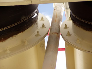
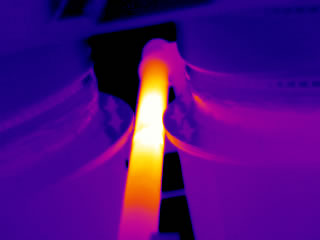
Often, engineering designs on switchgear enclosures and other electrical equipment do not take into consideration the interaction of non-current carrying ferrous devices within electro-magnetic fields. In some cases, these situations can pose safety hazards when the affected component is in contact with combustible materials or heats structures that are accessible to human contact. When faced with perplexing heat patterns on components that should not be hot, inductive heating may be to blame.
Visit Infraspection Institute Web Site
October 31, 2005
Sponsored by:
![]()
Frequency of Infrared Inspections of Electrical Equipment
“How often should electrical systems be thermographically inspected?” Historically, accepted industry practice has recommended that infrared inspections be performed annually; however, site specific conditions may dictate considerably shorter intervals for some equipment or facilities.
According to the 2002 Edition of NFPA 70B Recommended Practice for Electrical Equipment Maintenance, “Routine infrared inspections of energized electrical systems should be performed annually prior to shutdown. More frequent inspections, for example, quarterly or semiannually, should be performed where warranted by loss experience, installation of new electrical equipment, or changes in environmental, operational, or load conditions.”
Semi-annual infrared inspections may also be prudent where unscheduled outages of electrical equipment could pose significant environmental or safety hazards, or result in catastrophic damage to other systems or components.
Because infrared inspections are only effective when electrical system components are energized, it is imperative to perform infrared inspections when subject equipment is operational. For facilities with seasonal equipment such as heating and cooling systems, it may be necessary to schedule infrared inspections on several different days spread throughout the calendar year.
As always, infrared inspections of electrical systems should only be performed by properly trained and certified thermographers following all appropriate safety precautions. For information on thermographer training and certification or to obtain a copy of the Guideline for Infrared Inspection of Electrical and Mechanical Systems, contact Infraspection Institute at 609-239-4788 or visit us online at: www.infraspection.com.
To obtain a copy of NFPA 70B, contact the National Fire Protection Association at 1-800-344-3555 or visit them online at: www.nfpa.org.
November 07, 2005
Sponsored by:
![]()
Gauging When IR Inspection Window Opens/Closes
Solar-driven infrared inspections of insulated structures and roofs must be performed when sufficient Delta T is present. Knowing how to gauge when this window of opportunity is present is critical to the accurate collection of data.
Infrared inspections of structures often utilize solar loading to create temperature differentials necessary for the inspection. Common applications include moisture inspections of roofs and walls, structural inspections of CMU walls, and gauging product levels in tanks and silos. Often, these types of infrared inspections are performed during evening hours following a sunny day while the structure is cooling.
The time frame during which solar-driven infrared inspections may be accurately performed is often referred to as the ‘scanning window’. The scanning window is said to be open when conditions permit the collection of accurate data. A number of interdependent factors will determine when the scanning window opens and closes. These include, but are not limited to: target construction, amount of solar loading, local weather conditions, and imager sensitivity.
To determine when the scanning window opens, a thermographer should initially isolate an area with a small delta T indicative of an exception. For moisture inspections, this might be an area that is confirmed to be minimally wet. Using this area as a benchmark, the thermographer can periodically re-check this area during the inspection to determine if a Delta T remains. In general, the disappearance of a Delta T in the benchmark area will indicate that the scanning window is closing.
November 14, 2005
Sponsored by:
![]()
Imager Operational Check Prior to Inspections
Many infrared applications standards require that infrared test equipment be within calibration prior to the conduct of an inspection. Although performing a full calibration on daily basis is impractical, performing some simple operational checks can help to ensure that equipment is functioning properly.
Prior to commencing an infrared inspection, a thermographer should set up his/her equipment by:
- Checking imager optics for cleanliness
- Ensuring that batteries are fully charged
- Inspecting power and video cables/connectors for electrical integrity
- Allowing imager to stabilize with ambient temperature.
After completing the above, power-up the thermal imager and note that the imager initializes properly. Once the imager has initialized, adjust imager controls to normal temperature range. Focusing on a high emittance target such as a tabletop or a wall covered with latex paint, check the monitor for image clarity. If the image has inexplicably hot or cold pixels, perform a non-uniformity correction.
Once the image appears clear, a small Delta T can be created by placing one’s hand on one of the above high E surfaces for a few seconds. After removing the hand, image this same area and note the thermal pattern and its intensity. With a properly operating thermal imager, the thermal pattern of the hand should be clearly visible and last for at least one minute.
For more information on thermographer training and certification, contact Infraspection Institute at 609-239-4788 or visit us online at www.infraspection.com.
November 21, 2005
Sponsored by:
![]()
Infrared Inspections to Detect Latent Moisture
As interest in building remediation has increased, thermography has become a common tool for helping to detect moisture damage. Knowing when and how to conduct an infrared inspection is key to success.
Water infiltration into buildings can have devastating effects on building materials. Left untreated, latent moisture can cause excess energy loss, mold growth and/or structural failure. Latent moisture also causes changes in the thermal capacitance and conductivity of materials.
Prior to performing an infrared inspection, determine the best vantage point for imaging. Insulated roofs and exterior building finishes such as EIFS are traditionally inspected from the exterior of the building. Interior inspections are usually effective when moisture is affecting interior finishes of the building such as drywall. Thermal imaging may not be effective for low emittance targets.
Next, choose an appropriate time to ensure that a detectable Delta T will be present. For roofs and building exteriors, best results are usually obtained during evening hours following a sunny day. As an alternative, inspections may also be performed when there is an inside/outside temperature differential of at least 10Cº. In some cases, inspections performed from the interior may be performed with a smaller Delta T.
Thermal signatures associated with latent moisture will vary with type of building material and the amount of moisture contained therein. Depending upon vantage point and time of inspection, exceptions caused by latent moisture may show as either hot or cold thermal anomalies. These anomalies may be amorphously shaped, mottled, or correspond to the size and shape of absorbent materials. All thermal data should be correlated with invasive testing to ascertain moisture content of inspected areas.
November 28, 2005
Sponsored by:
![]()
How Much Certification Do You Need
Certification and levels thereof are one of the most frequently discussed issues in thermography. With few standards addressing certification, purchasers of infrared inspection services and thermographers often ask, “How much certification is necessary?”
Due to a variety of definitions, certification can have different meanings. As it is used in thermography, certification generally means, “to declare something to be true and/or to attest by issuing a certificate to.”
The American Society for Nondestructive Testing document, SNT-TC-1A provides suggested curricula and experience for under the Thermal/Infrared test method. Recommended curricula and the classroom hours are listed below; these should be modified to meet an employer’s needs.
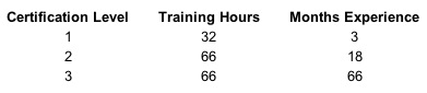
In short, it is up to an employer to determine his/her client’s needs for and to set certification requirements accordingly.
Taken at face value, certification generally indicates one’s level of formal training. This training, combined with experience and knowledge of the system or structure being inspected determine a thermographer’s qualifications.
In a larger sense, certification is a measure of a thermographer’s professional qualifications. It is therefore incumbent on the professional thermographer to achieve the highest level of certification possible. The rewards for doing so are both personal and professional and can provide significant financial and competitive advantages.
Infraspection Institute has been training and certifying professional infrared thermographers since 1980. Our Level I, II, and III Certified Infrared Thermographer® training courses are fully compliant with ASNT and industry standards. Students may choose from open-enrollment and convenient web-based Distance Learning Courses. For more information or to register for a class, call 609-239-4788 or visit us online at www.infraspection.com.
December 12, 2005
Sponsored by:
![]()
Ambient Temperature & Radiometer Accuracy
Many who live in cold climates are in the habit of allowing their automobile to warm up before driving. For accurate temperature measurement, one should allow sufficient time for a radiometer to equalize with ambient temperature.
When performing non-contact temperature measurements, many thermographers correct for error sources due to emissivity, reflectivity and transmissivity. One error source that is often ignored is the temperature of the radiometer itself. Depending upon design, radiometer operating temperature can significantly affect measurement accuracy.
Radiometers are calibrated under controlled laboratory conditions at stable ambient temperatures. To help ensure measurement accuracy, quality radiometers are constructed with internal temperature sensors. These sensors allow the radiometer’s firmware to correct for operation at different ambient temperatures.
When performing non-contact temperature measurements, radiometers should always be allowed to stabilize with ambient air temperature. Additionally, one should ensure that the radiometer’s lens is clean and free of condensation.
Infraspection Institute has been training and certifying professional infrared thermographers since 1980. Our Level I, II, and III Certified Infrared Thermographer® training courses are fully compliant with ASNT and industry standards. Students may choose from open-enrollment and convenient web-based Distance Learning Courses. For more information or to register for a class, call 609-239-4788 or visit us online at www.infraspection.com.
December 19, 2005
Sponsored by:
![]()
Files Worth Saving
With year-end in sight, many will begin the annual process of clearing out files and getting ready for the upcoming year. In this week’s Tip, we share some thoughts on files that you may wish to keep.
Recently, while cleaning out some old personal files, my family came across a classic Christmas poem that had been transcribed by my grandmother many years ago. The poem titled, “Jest ‘Fore Christmas” is a 19th century Eugene Field poem that recalls simpler times. The poem’s central character is a boy named William. It is likely that this particular work had caught my grandmother’s attention since her husband and oldest son were both named William.
Now as we read the yellowed and fragile notepaper that bears our grandmother’s distinctive handwriting, we can recall many fond memories of her and our family, especially during Christmas.
With the holidays and busy year end schedules upon us once again, we invite you to take the time to make special memories with family and friends and to file them in your heart so that you may easily find them in the future.
As we enjoy this holiday season, we extend a heartfelt Thank You to all of our readers, friends, and associates throughout the world for everything that you do for us all year long. May your holidays be filled with peace and joy and your New Year with good health and happiness.
~ Jim & Chris Seffrin
Jest ‘Fore Christmas
by Eugene Field (1850-1895)
Father calls me William, sister calls me Will,Mother calls me Willie, but the fellers call me Bill!Mighty glad I ain’t a girl—ruther be a boy,Without them sashes, curls, an’ things that ‘s worn by Fauntleroy!Love to chawnk green apples an’ go swimmin’ in the lake—Hate to take the castor-ile they give for bellyache!’Most all the time, the whole year round, there ain’t no flies on me, But jest ‘fore Christmas I ‘m as good as I kin be!
Got a yeller dog named Sport, sick him on the cat;First thing she knows she doesn’t know where she is at! Got a clipper sled, an’ when us kids goes out to slide,’Long comes the grocery cart, an’ we all hook a ride! But sometimes when the grocery man is worrited an’ cross,He reaches at us with his whip, an’ larrups up his hoss, An’ then I laff an’ holler, “Oh, ye never teched me!” But jest ‘fore Christmas I ‘m as good as I kin be!
Gran’ma says she hopes that when I git to be a man, I ‘ll be a missionarer like her oldest brother, Dan, As was et up by the cannibuls that lives in Ceylon’s Isle, Where every prospeck pleases, an’ only man is vile! But gran’ma she has never been to see a Wild West show, Nor read the Life of Daniel Boone, or else I guess she ‘d know That Buff’lo Bill an’ cowboys is good enough for me! Excep’ jest ‘fore Christmas, when I ‘m good as I kin be!
And then old Sport he hangs around, so solemnlike an’ still, His eyes they seem a-sayin’: “What’s the matter, little Bill?” The old cat sneaks down off her perch an’ wonders what’s become Of them two enemies of hern that used to make things hum! But I am so perlite an’ tend so earnestly to biz, That mother says to father: “How improved our Willie is!” But father, havin’ been a boy hisself, suspicions me When, jest ‘fore Christmas, I ‘m as good as I kin be!
For Christmas, with its lots an’ lots of candies, cakes, an’ toys, Was made, they say, for proper kids an’ not for naughty boys; So wash yer face an’ bresh yer hair, an’ mind yer p’s and q’s, An’ don’t bust out yer pantaloons, and don’t wear out yer shoes; Say “Yessum” to the ladies, and “Yessur” to the men, An’ when they ‘s company, don’t pass yer plate for pie again; But, thinkin’ of the things yer ‘d like to see upon that tree, Jest ‘fore Christmas be as good as yer kin be!
December 27, 2005
Sponsored by:
![]()
Determining Neutral Plane Location
Thermographically detecting air leakage sites within buildings is dependent upon proper site and weather conditions and imaging vantage point. Determining the location of a building’s neutral plane is key to ascertaining the correct vantage point for thermal imaging.
Air leakage can account for significant energy losses within buildings. Such losses occur as unconditioned air moves through the building’s thermal envelope into conditioned spaces. For heated low-rise structures, air typically infiltrates at lower elevations and exfiltrates at higher elevations. Simply defined, the neutral plane is the elevation within the structure where no air leakage occurs since indoor/outdoor air pressure is balanced.
Determining neutral plane location can often be more art than science. Among the many factors that influence the location of the neutral plane are: building construction, building height, inside/outside temperature differential, and the operation of the building’s HVAC system. Wind speed and direction can also influence the location of a neutral plane.
To help determine the location of a building’s neutral plane, use your thermal imager to investigate likely air leakage sites such as electrical receptacles on exterior walls. If you detect evidence of air infiltration at these sites, move upward to the next floor of the structure. Once above the neutral plane, evidence of air leakage sites will generally not be thermographically detectable unless a negative pressure is created with a blower door or the building’s HVAC system.
Infraspection Institute has been training and certifying infrared thermographers worldwide since 1980. Infrared inspection of building envelopes is covered in depth in all of our Level I training courses. For more information on our Certified Infrared Thermographer® or Distance Learning courses, call us at 609-239-4788 or visit www.infraspection.com.